background image


COFFEE PREPARATION PROCEDURES 


1) 

Place filter into brew basket. 

 
2) 

Put the proper amount of coffee into the filter. 

 
3) 

Slide the brew basket into holder. 

 
4) 

Place empty decanter on warmer located directly under the brew basket and turn corresponding warmer switch to ON 
position. 

 
5) 

Press “Brew” switch,  switch will beep, and amber light will blink. 

 
6) 

Hot water will be delivered through the sprayhead. This distributes the hot water evenly over the coffee bed within the brew 
basket. The coffee brew will drain from the brew basket into the decanter below. 

 
7) 

The resultant coffee brew should be crystal clear and have the desired properties attainable through excellent extraction. 

 
8) 

TURN OFF WARMER WHEN NOT IN USE. (Red light indicates warmer is on.) 

 
9) 

To clean brew basket simply remove from brew rails and dump filter into waste basket. The brewing process, as described 
above, can now be started again. 


DELIMING 


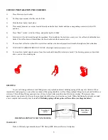
To prevent liming problems in tank fittings remove sprayhead and insert deliming spring all the way into the tank. When 

inserted into tank properly, no more than ten inches of the spring should be visible at the sprayhead fitting. Saw back and forth five or 
six times. This will keep fittings open and clear of lime. In hard water areas this should be done everyday. This process takes 
approximately one minute. In all areas the sprayhead should be cleaned at least once a week. Where bad liming has already occurred, 
a new complete tank assembly may be installed.

 Deliming spring will not go in overflow orifice. (see diagram below) 


DELIMING SPRING PN 120127 (INCLUDED)        


Overflow

orifice 

Sprayhead 

outlet 


WARRANTY 


Refer to Warranty Agreement between TDL Group, BBC Sales, and Newco Enterprises. 


5

Содержание DB2A

Страница 1: ... BREWER AUTOMATIC DB2A INSTALLATION OPERATION AND TROUBLESHOOTING MANUAL FOR DB2A AUTOMATIC BREWER WITH WARMERS POUR OVER Model DB2A 8 1 2 W x 18 D x 33 H 4700 Total Watts 23 3 AMPS 120 208 V Ship Wt approx 54 LB s Decanters Not Included ...

Страница 2: ...2 ...

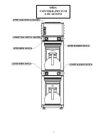
Страница 3: ...DB2A CONTROL SWITCH LOCATIONS 3 ...

Страница 4: ...n side of brewer 2 Adjust timer to deliver desired amount of water Timer is located behind front access panel To brew into a regular 64 oz decanter little adjustment should be needed Turn timer dial clockwise to increase volume of water and counter clockwise to decrease volume 3 Place the decanters under brew baskets turn on bottom two warmers and using brew switches brew three brew cycles or unti...

Страница 5: ...To clean brew basket simply remove from brew rails and dump filter into waste basket The brewing process as described above can now be started again DELIMING To prevent liming problems in tank fittings remove sprayhead and insert deliming spring all the way into the tank When inserted into tank properly no more than ten inches of the spring should be visible at the sprayhead fitting Saw back and f...

Страница 6: ...hi limit thermostat then the outgoing terminal VIOLET BLACK on the hi limit thermostat 1 A If correct voltage is present at the tank heater terminals and water in tank is not being heated replace the tank heater B If voltage is not present at the tank heater terminals refer to step 2 C If incorrect voltage is present at the tank heater terminals check voltage at outlet 2 A If voltage is present on...

Страница 7: ...lter and coffee in brew basket 1 Insert correct filter 2 Refer to DRIPPING Step 1 3 Filter should be centered in brew basket and coffee bed should be level SOLENOID CHATTER OR HOWLING 1 Brewer connected to hot water line 2 Vibration 3 High water pressure 4 Water hammer 5 60 cycle vibration 1 Incoming water line 2 If brewer is on a metal stand or counter neither the bottom pan nor copper tubing to ...

Страница 8: ...DB2A ACCESS PANEL COMPONENTS 8 ...

Страница 9: ...REPLACEMENT PART DIAGRAM FRONT VIEW 9 ...

Страница 10: ...55 54 1 33 32 3 47 4 34 REPLACEMENT PART DIAGRAM REAR VIEW 10 ...

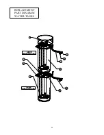
Страница 11: ...41 22 5 27 58 39 42 36 23 74 120079 UPPER TANK ASS Y 120069 LOWER TANK ASS Y REPLACEMENT PART DIAGRAM WATER TANKS 11 ...

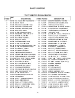
Страница 12: ...098 BRACKET LOWER INLET DB3A 18 120059 WRAPPER SPTWLD DB3A 55 120099 BRACKET UPPER INLET DB3A 19 120091 HARN WARM TIMER SWI DB3A 56 151590 CORD ASY 240V 30A CM BAR 20 781431 SWITCH BREWER START AMBER 57 201128 VALVE SHUTOFF 1 4 FLARE 21 781870 SWITCH TANK POWER GREEN 58 120075 TUBE ASS Y VENT LOWER TANK 22 704221 GASKET TANK SILICONE 59 201991 SOLENOID VALVE REPAIR KIT 23 704119 TANK ONLY K STYLE ...

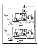
Страница 13: ...NG THERMOSTAT VIO WARMER WH BK WH WH WH WH WH BK RD BK RD FILL SOLENOID FILL SOLENOID TIMER TIMER 5 4 2 1 6 6 BK YEL BK YEL VIO VIO VIO RD RD RD VIO BK YEL BK BK VIO VIO RD VIO RD VIO RD WH L1 L2 N E L1 BK VIO BK BK VIO GREY BK WH VIO RD BK BK BK BK YEL BK VIO VIO BK BK VIO BK VIO BK VIO BK BK BL VIO BK BK BK UPPER ELEMENT MIDDLE WARMER LOWER WARMER LOWER LOWER BREW UPPER BREW LOWER ELEMENT BK RED...

Отзывы: