WFU12-4C
14
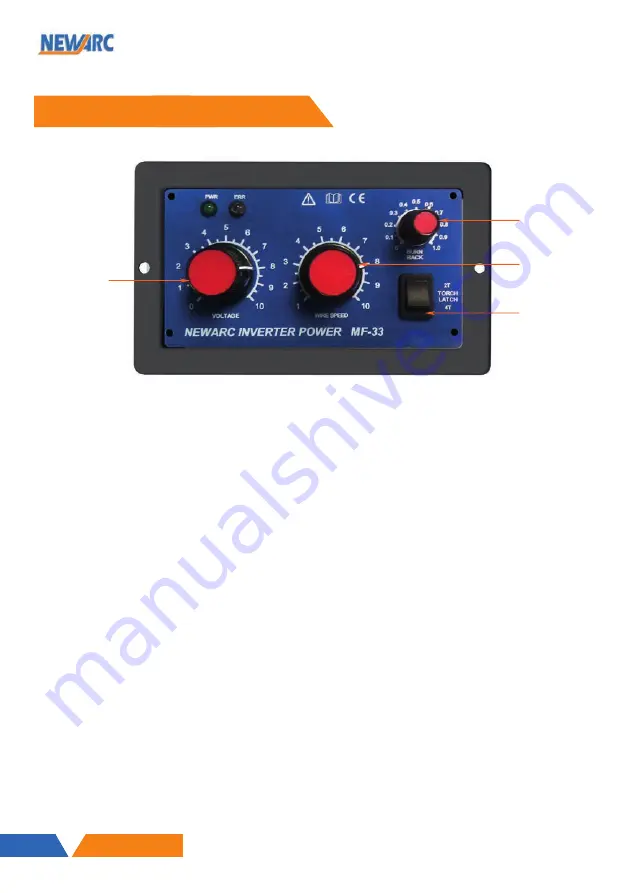
1.6 Overview of Panel MF33
WFU12-4C
12
1.
Burn back adjustment
- This determines how much of the wire is left sticking out of the contact tip
when welding is stopped. Too much wire and there is a chance of it 'freezing' in the weld pool as
it cools, too little and there is a chance that the wire will burn back into the contact tip, necessi-
tating changing of the tip. Adjusting the control anti-clockwise increases the amount of wire stick-
ing out of the tip and adjusting it clockwise reduces it.
2.
Wire speed control
- Adjusts the speed of the wire feed system up to a maximum of 23m/min.
3.
Voltage control
- Controls the welding voltage when used in conjunction with a Newarc R4/5000
multi-process or constant voltage power source.
4.
Latch
- Changes the mode of operation of the MIG torch switch between 2T and 4T. In 2T, the
MIG torch switch is pressed to start welding and released to stop. In 4T, the torch switch is pressed
and released to start welding and pressed and released again to stop welding.
4.4 - MIG Welding
•
It is assumed that the wire and welding torch have been fitted as per the installation part of this
manual.
•
Set the Voltage control and wire speed controls proportional to the thickness of metal to be
welded.
•
Select the welding torch mode required.
•
Ensure the gas cylinder is turned on and the flow-meter or regulator is set to give approximately 15
to 20 Litres per minute. (30 to 40 cubic feet per hour).
•
Until you are familiar with the machine it is preferable to start welding on a piece of waste material
the same type and thickness as the work-piece, adjust the voltage control (if fitted), wire feed and
gas flow until the required welding condition is achieved.
When used with the Newarc power sources all the controls can be adjusted whilst welding without dam-
aging the machine.
4.3 - Operational Controls for MF33 Front Panel
3
1
2
4
SECTION 4 — OPERATION
Front View
Panel layout
1. Burn back adjustment
2. Wire speed control
3. Voltage control
4. Latch


