background image

6.7. 

Calibration Adjustment Example 


1.


Example:  E-RAD set to 1800 ftlbs = Transducer reads out 1750 ftlbs. 

2.


All though this value is /- 3%, we can narrow this difference. 

3.


By following steps 1 through 7 in section (6.5) re-connect to the E-
RAD calibration software. 

4.


Once connected, in the percentage intervals find the % value that is 
closest to the torque value that you are trying to adjust. 

5.


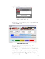
For our example of 1800 ftlbs, 70% in (figure 9) is the value that we 
are going to adjust. 

6.


To bring the actual torque up from 1750 to 1800 ftlbs, we are going to 
change the 70% value from 1790 down to 1760.   


Remember


the general rule that to bring a torque value up, we must 

lower the calibration value and to lower a torque value, we must raise the 
calibration value. 


7.


Save Settings. 

8.


Turn your E-RAD off, unplug the communication cable and re-start 
your E-RAD. 

9.


With the torque value on the controller set to 1800 ftlbs, complete a 
torque cycle on the calibration stand and verify the actual torque read 
by the transducer to the torque value set on the controller.   

10.


If you are still not satisfied you may repeat these steps. 


Notes: 


1.


Generally for every (1) calibration value you change, the actual output torque 
will be adjusted by 2.  For Example… 

2.


If the value you are trying to change is right in between to percentage intervals 
(20% / 30%), make adjustments to both percentage values. 

NOTE:


 By adjusting both of these values, this may effect the accuracy of other 

torque settings on your E-RAD. 


7. Data Retrieval 


E-RAD torque systems store the records of up to 350 successful torque cycles. 
The data retrieval system does not record 

“FAILED”

 torque cycles and will only 

record cycles that 

“PASS”

.  Below is a detailed outline on how to install and 

operate your data retrieval program. 


15

Содержание E- ER 700

Страница 1: ...LEADING MANUFACTURER OF ADVANCED TORQUE SYSTEMS E RAD USER MANUAL ELECTRONIC BATTERY PNEUMATIC ELECTRIC ...

Страница 2: ...t reaction arm before full torque is applied Equal power in forward and reverse Convenience and cost effective use of same tool for break away and final torque Imagine the freedom no air lines no power cords The lightweight design of the B SERIES makes them ideal for any application especially where compressed air and electricity are not readily available Advanced gearbox design PATENTED planetary...

Страница 3: ...ure 10 6 1 Calibration Equipment 10 6 2 Calibration Period 10 6 3 Calibration overview 10 6 4 Calibration Software 11 6 4 1 Installation 11 6 4 2 Uninstalling E RADCal program 11 6 5 Calibration Software Operation 11 6 6 Calibration Testing 14 6 7 Calibration Adjustment 15 7 Data Retrieval 15 7 1 Data Retrieval Operation 16 Appendix A Sample Calibration Certificate 19 Appendix B Option 1 Operation...

Страница 4: ...WORLD TECHNOLOGIES INC OR YOUR LOCAL DISTRIBUTOR IMMEDIATELY IMPORTANT WHEN USING A POWER PLUG ADAPTER MAKE SURE THE EARTH GROUND PIN IS PRESENT AND CONNECTED IN THE ADAPTER NEW WORLD TECHNOLOGIES INC DOES NOT RECOMMEND REAPLCING THE SUPPLIED POWER CORD IN THE EVENT THE POWER CORD IS REPLACED MAKE SURE THE NEW POWER CORD HAS AN EARTH GROUND PIN ...

Страница 5: ...ned to provide a high degree of accuracy and repeatability using our patented legendary gear box design and the precision of an electronic motor Capable of data collection angle measurement accuracy of 3 and torque values up to 4000 ft lbs RAD E SERIES offer an affordable solution for electronic bolting needs 1 ...

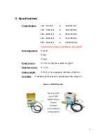
Страница 6: ... 675 4050 Nm 800 4000 lb ft or 1000 5400 Nm Custom torque ranges are available up upon request Units Supported Æ Lb Ft Æ Nm Æ Kg F Power Source Æ 115V AC 10A or 220V AC 5A Stated Accuracy Æ 3 Cables Length Æ 15 ft 4 5m Standard 20 ft 6m 25 ft 7 6m Controller Æ Weather proof pelican or upright steel case Figure 1 Figure 1 E RAD System 2 ...

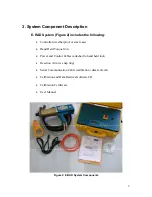
Страница 7: ...atherproof or steel case Hand Held Torque Gun Power and Control Cables attached to hand held tool Reaction Arm w snap ring Serial Communication Cable calibration data retrieval Calibration and Data Retrieval software CD Calibration Certificate User Manual Figure 2 E RAD System Components 3 ...

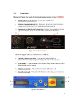
Страница 8: ...ed interface between the Controller and the Hand Held Tool 3 1 2 Figure 3 Controller Connections Below in Figure 4 the user interface is outlined 1 3 Button Touch Pad Overlay Provides the user the ability to increase decrease torque angle and change the units of measurement 2 LCD Display Visual feedback of the torque setting torque achieved preset angle and direction of rotation 3 Main Power Switc...

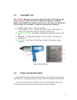
Страница 9: ...x display if in question of direction 3 System Ready light Green light will illuminate when the tool is ready for use 4 Fail light Red light will illuminate when the tool fails to complete the torque cycle 5 Pass light Green light will illuminate when the tool completes torque operation 3 2 4 1 5 Figure 5 Hand Held Tool 3 3 Power and Control Cables Both power and control cables are hard wired from...

Страница 10: ...t is calibrated with compliance to ISO 10012 using equipment that is calibrated according to known industry accepted standards traceable via NIST standards See appendix A for a Calibration Certificate Sample 4 System Setup Caution Before plugging in main power cord or Hand Held Tool cables make sure the main power switch is in the OFF position Failure to comply may result in equipment failure or e...

Страница 11: ...o the notch in the controller Push the connector in forward and turn clock wise at least turn until the plug locks into the connector on the case 3 Connect main AC power plug to an appropriate AC power source 115V AC or 220V AC according to the model 4 Make sure serial communication cable is disconnected Caution Make sure that all connectors are secured prior to turning the power switch ON Failure...

Страница 12: ...d held tool is illuminated The display will flash model and firmware version for 2 seconds then displays on the top row last used torque setting and on the bottom row and the actual torque reading To increase torque setting press on the INCREASE arrow If maximum value of torque setting is reached the displayed value does not change If the buttons are pressed briefly the torque changes by a single ...

Страница 13: ...ed o To clear an error or a failed indicator illumination set the direction switch to REVERSE bottom line of LCD displays REVERSE Any error or failed indicator illumination is cleared Pressing the Trigger causes the tool to operate in the reverse direction as long as the Trigger is pressed o If the tool is unable to reach the correct torque switch the Direction switch to reverse back the bolt off ...

Страница 14: ...posed to extreme temperatures Rough handling or significant shock to the system Tool seems to be exceeding the accepted torque error or tolerance margin 6 3 Calibration overview To perform an E RAD calibration the controller must be connected to a PC with the serial communication cable and may require the Key Span USB to Serial Port Adapter which is supplied by New World Technologies with every E ...

Страница 15: ...any reason the calibration software needs to be removed follow these steps Click on Start Menu Select Control Panel Select Add Remove Programs Find and select E RAD Cal in the program list and click on the Remove Button to remove the software from your computer 6 5 Calibration Software Operation Before launching the calibration software make sure the calibration system is set up as follows Connect...

Страница 16: ...cted the connect button will turn orange and read disconnect Figure 9 6 Click the dark green Enter Calibrate Mode button and the calibration values will appear under the intervals and the Enter Calibration Mode button will turn dark orange 7 To begin calibration click the percentage intervals in a sequential order according to the motor power percentage desired The buttons background will change f...

Страница 17: ...s display take a couple more readings to make sure that the readings are in the same value range and take the average of the values 12 In the Calibration Torque table place the cursor in the text box underneath the label value of 7 and type in the average torque value calculated in the previous step Press Enter Attention Enter must be pressed after every entry otherwise the value will not be recor...

Страница 18: ...ail light Record the value displayed on the transducer s display 4 Set the tool in REVERSE and depress the trigger for a few seconds and loosen the joint simulator Repeat step 3 After the second reading record the average value of the 2 readings observed on the transducer s display 5 Verify the actual torque that is read out by the transducer against what the E RAD is set to achieve 6 To adjust th...

Страница 19: ...ur E RAD off unplug the communication cable and re start your E RAD 9 With the torque value on the controller set to 1800 ftlbs complete a torque cycle on the calibration stand and verify the actual torque read by the transducer to the torque value set on the controller 10 If you are still not satisfied you may repeat these steps Notes 1 Generally for every 1 calibration value you change the actua...

Страница 20: ...software onto your computer 4 After the setup is complete unless otherwise specified the Data Retrieval Software will be installed in My Computer Program Files E RAD Data From here copy the short cut of the E RAD Data Logger and paste this onto your desktop for easy accessibility 7 1 Data Retrieval Operation 1 Before opening the E RAD Data Retrieval Software connect your E RAD Control Box to your ...

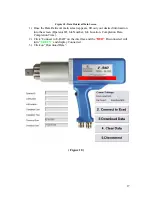
Страница 21: ...een appears fill out your desired information into the screen Operator ID Job Number Job Location Completion Date Completion Time 2 Click Connect to E RAD on the interface and the RED Disconnected will turn GREEN and display Connected 3 Click on Download Data Figure 10 17 ...

Страница 22: ...der any file name and in your desired location in your computer and your bolting specs are now recorded and accessible in your system 6 After the download is complete return to the Data Retrieval Software Figure 10 and click on Clear Data 7 Your E RAD has now transferred all data to your personal computer and the memory is clear and ready for another sequence of bolting application 18 ...

Страница 23: ...Appendix A Sample of Calibration Certificate 19 ...

Страница 24: ...ypad and switch position programming Programming a switch position 1 Place the switch knob to the position to be programmed 2 Turn the key to the right in this position key removal in not allowed 3 Press increase or decrease to reach the torque setting required 4 if more position are required to be programmed turn the switch know to the next position and repeat step 3 5 After the last position pro...

Страница 25: ...ser This is outlined below 9 If the angle is set to zero than no angle movement will take place 9 If the torque is set to zero no initial torque will take place and the tool will only perform the programmed angle movement only The tool will walk up and seat the reaction arm and then complete the angle movement 9 If both the torque and angle are set to zero the tool will not operate 21 ...

Страница 26: ...decrease buttons you will be able to scroll through the different units of measurement To change the position of the arrow which will allow you to adjust either the initial torque units of measurement or angle movement press the Units button 7 to move this arrow to the right of your desired feature that you would like to adjust 5 This will indicate what angle movement the E RAD is programmed to pe...

Страница 27: ...t to zero no initial torque will take place and the tool will only perform the programmed angle movement only The tool will walk up and seat the reaction arm and then complete the angle movement 9 If both the torque and angle are set to zero the tool will not operate This can be used as a safety lock out setting on the selector switch Figure 1 1 User Interface 1 This indicates the initial torque v...

Страница 28: ...o scroll through which feature they would like to adjust This arrow is explained in 4 above Figure 1 2 Selector Switch Positions 1 through 8 can be programmed with your specific torque angle values that you input into the system To program these setting simply place the dial on the position of your choice program in the desired torque angle settings that are required and then repeat this for all o...

Страница 29: ...ix D Contact Information New World Technologies Inc 30580 Progressive Way Abbotsford B C Canada V2T 6Z2 Tel 604 852 0405 Toll Free 1 800 983 0044 Fax 604 852 0269 Email info radtorque com www radtorque com 25 ...

Страница 30: ...e date of original repair To qualify for the above mentioned warranties written notice to New World Technologies Inc must be given immediately upon discovery of such defect at which time New World Technologies Inc will issue an authorization to return the tool The defective item must promptly be returned to New World Technologies Inc all freight charges prepaid When returning a tool the reaction a...

Страница 31: ...roven to be successful all over the world in such industries as oil and gas petrochemical mining aerospace and manufacturing we continue to invest in and employ the latest technology to achieve the highest level of innovation quality and performance which has resulted in multiple patents for our products NEW WORLD TECHNOLOGIES INC 30580 Progressive Way Abbotsford BC V2T 6Z2 Canada T 604 852 0405 F...

Отзывы: