background image


P l e a s e   G i v e   P a r t   N o . ,   D e s c r i p t i o n   a n d   U n i t   S e r i a l   N o .


HIGHWAY EQUIPMENT COMPANY


21 

97372-B 

Page Rev. A 


INSTALLATION INSTRUCTIONS CONTINUED 


HYDRAULIC PUMP INSTALLATION 


A mounting bracket for the hydraulic pump is shipped with the spreader.  It may be necessary to 
modify this bracket to fit your truck since many variable factors such as PTO make and model, muffler 
position, transmission make and model, etc., all affect the mounting position.  DO NOT WELD THE 
BRACKET TO THE TRUCK FRAME.  To do so may void the truck manufacturer’s warranty. 


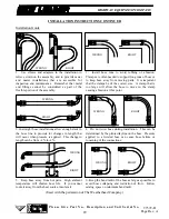
Position the mounting bracket so that the pump drive shaft will be as straight as possible.  In no case 
should the angle of any universal joint exceed 15º.  The pump shaft and PTO shaft should be parallel.  
(Figure 1) 
 
HYDRAULIC PUMP DRIVE SHAFT INSTALLATION 


The pump drive shaft included may be too long for some installations.  It may be cut and redrilled as 
necessary.  When redrilling the shaft, be sure that universal joints are properly “timed”, as shown in 
Figure 1. 


Install the slip joint at the end of the pump drive shaft.  Failure to install the slip joint will result in 
bearing failure in pump, PTO or both. 


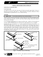
Figure 1 - Timing of Universal Joints 


RADAR & CONTROLLER INSTALLATION 


See control manual for installation instructions of radar, control box and cable routing. 

Parallel Shafts 

Not To Exceed 
    15 Degrees 

Parallel Forks 

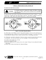
All holes in the truck cab walls, floor and firewall for control wires, hoses 
and cables are to be grommeted, plugged and sealed to prevent entrance of 
engine fumes, dust, dirt, water and noise. 
 

CAUTION


Содержание L3020G4

Страница 1: ...RAPIDS IOWA 52404 7052 PH 319 363 8281 www highwayequipment com FAX 319 632 3081 HIGHWAY EQUIPMENT COMPANY GENERAL MANUAL FOR MODEL L3020G4 SAFETY GUIDELINES INSTALLATION OPERATION MAINTENANCE TROUBLESHOOTING PARTS LIST Dealer Sticker This unit may have been built with SPECIAL FEATURES Provide SERIAL NUMBER when ordering parts SERIAL NO _________________ ...

Страница 2: ......

Страница 3: ...R 97372 B EFFECTIVE 6 2006 Starting with Serial No 122208 HIGHWAY EQUIPMENT COMPANY 1330 76TH AVE SW CEDAR RAPIDS IOWA 52404 7052 PHONE 319 363 8281 FAX 319 632 3081 www highwayequipment com BUILDING THE BEST SINCE 1939 Copyright 2003 Highway Equipment Company Inc ...

Страница 4: ...lation 21 Mounting Spreader Body 22 Spinner 25 Inverted V 25 Fender Installation 26 Electric Dump Valve Control 26 Hydraulic Hose Installation 27 Electrical Connections 30 Light Installation 30 Spinner Sensor 30 Filling Hydraulic System 30 Checking Installation 30 Initial Start Up 31 Field Testing 32 General Operating Procedures 33 Lubrication Maintenance 34 Hydraulic System 34 Hydraulic Hose 35 C...

Страница 5: ...n Shields 52 Conveyor Idler 54 Conveyor Drive 55 Encoder 56 Conveyor Chain Oiler 57 Wipers 58 Fenders 60 Inverted V 66 Cab Shield 67 Ladders 68 Hillside Flow Divider 69 Material Divider 70 Spinner Guards Shields 71 24 Hydraulic Fans 72 Spinner Sensor 74 Reservoir 75 Hydraulics Raven Control 76 Mark Series Control 80 Manual Dual Control 83 Twin Spinner Hydraulics 86 Pump Hydraulics 88 Gear Case 89 ...

Страница 6: ...INSERT NEW LEADER NL WARRANTY ...

Страница 7: ...TAB SAFETY ...

Страница 8: ...uct Support Department at 319 363 8281 It has been our experience that by following these installation instructions and by observing the operation of the spreader you will have sufficient understanding of the machine enabling you to troubleshoot and correct all normal problems that you may encounter Again we urge you to call your authorized dealer or our Cedar Rapids Product Support Department if ...

Страница 9: ...RTANT Is used for informational purposes in areas which may involve damage or deterioration to equipment but generally would not involve the potential for personal injury The need for safety cannot be stressed strongly enough in this manual At Highway Equipment Company we urge you to make safety your top priority when operating any equipment We firmly advise that anyone allowed to operate this mac...

Страница 10: ...ccurs Regardless of the care used in the design and construction of any type of equipment there are many conditions that cannot be completely safeguarded against without interfering with reasonable accessibility and efficient operation A CAREFUL OPERATOR IS THE BEST INSURANCE AGAINST AN ACCIDENT THE COMPLETE OBSERVANCE OF ONE SIMPLE RULE WOULD PREVENT MANY THOUSAND SERIOUS INJURIES EACH YEAR THAT ...

Страница 11: ... adhere to these 3 Remove the Liner A small bend at the corner or edge will cause the liner to separate from the decal Pull the liner away in a continuous motion at a 180 degree angle If the liner is scored bend at score and remove 4 Apply Safety Decal a Tack decal in place with thumb pressure in upper corners b Using firm initial squeegee pressure begin at the center of the decal and work outward...

Страница 12: ...Please Give Part No Description and Unit Serial No HIGHWAY EQUIPMENT COMPANY 9 97372 B Page Rev A SAFETY DECALS CONTINUED ...

Страница 13: ...ed use runaway vandalism theft and unexpected operation during start up 3 Do not read eat talk on a mobile phone or take your attention away while operating the unit Operating is a full time job 4 Stay out of the body while conveyor is operating If it is necessary to get into the body for any reason be sure all power is shut off vehicle brakes are set and the engine starting switch is locked and k...

Страница 14: ...inner violently Stay out of discharge area 11 Inspect spinner fins spinner frame mounting and spinner fin nuts and screws every day Look for missing fasteners looseness wear and cracks Replace immediately if required Use only new SAE grade 5 or grade 8 screws and new self locking nuts 12 Inspect all bolts screws fasteners keys chain drives body mountings and other attachments periodically Replace ...

Страница 15: ...ow instructions and precautions given by the manufacturer or supplier of materials to be spread Improper selection application use or handling may be hazardous to people animals plants crops or other property 19 Cover all loads that can spill or blow away Do not spread dusty materials where dust may create pollution or a traffic visibility problem 20 Turn slowly and be careful when traveling on ro...

Страница 16: ... wrench a wrench instead of a hammer not only can damage the equipment being worked on but can lead to serious injuries USE THE PROPER TOOLS 4 Before attempting any maintenance work including lubrication shut off power completely DO NOT WORK ON RUNNING MACHINERY 5 When guards and covers are removed for any maintenance be sure that such guards are reinstalled before unit is put back into operation ...

Страница 17: ...ld not be inhaled 11 When batteries are being charged or discharged they generate hydrogen and oxygen gases This combination of gases is highly explosive DO NOT SMOKE around batteries STAY AWAY FROM FLAME don t check batteries by shorting terminals as the spark could cause an explosion Connect and disconnect battery charger leads only when charger is off Be very careful with jumper cables 12 Batte...

Страница 18: ...al Motor Vehicle Safety Standard FMVSS No 108 and all applicable local and state regulations 4 When selecting a PTO to drive hydraulic pump do not use a higher percent speed drive than the Truck PTO Pump Match Graph indicates in the Installation section of this manual Too high a percent PTO will drive pump at excessive speed which can ruin the pump but more importantly will overheat the hydraulic ...

Страница 19: ...dge bead weld is not a satisfactory weld for this service Use dry E6013 or E7018 rod for normal steels On stainless steel bodies use SAE grade 5 bolts welding is recommended if type 308 welding rod is available 7 Install controls so they are located for convenient use Position them so they do not interfere with any vehicle control and they do not interfere with driver or passenger or with access t...

Страница 20: ...TAB OP MAINT ...

Страница 21: ...l system The hydraulic pump which provides the hydraulic power is a gear type pump and is driven by means of a transmission PTO The conveyor runs the full length of the hopper bottom to deliver material to the spinners through an adjustable metering gate at the rear of the hopper body The conveyor is driven by two orbital type hydraulic motors mounted to a 6 to 1 ratio spur gear case The standard ...

Страница 22: ...59 274cm CT 14 4 27 m 196 498cm 168 427cm 159 404cm 120 305cm CT 15 4 57 m 208 528cm 180 457cm 171 434cm 130 330cm CT 16 4 88 m 220 559cm 192 488cm 183 465cm 138 351cm CT Capacities Struck Cubic Yards Meters3 Cubic Feet Body Length 102 Wide Body 88 Wide Body Spreader Weight Approx Pounds As Shipped 10 3 05 m 7 8 5 9 209 6 6 9 5 3 187 3 3875 lbs 11 3 36 m 8 6 6 6 232 1 7 7 5 9 207 2 3945 lbs 12 3 6...

Страница 23: ...these factors be made This matching is called sizing 1 Correct sizing requires accurate and complete information A Engine governed operating speed B Transmission make and model C PTO Data 1 Make and Model of PTO 2 PTO percentage of Engine RPM 3 Direction of PTO Rotation Engine Direction or Opposite of Engine Direction NOTE It may be necessary to select a higher percentage PTO or a larger pump than...

Страница 24: ... questions must be considered 1 Is the CA Cab to Axle dimension of the truck correct for the length of the spreader To answer this question see the Dimensions chart on page 20 This will assist in matching spreader to truck 2 Is the truck s GAWR Gross Axle Weight Rating and the GVWR Gross Vehicle Weight Rating adequate to carry the fully loaded spreader To answer this question refer to your New Lea...

Страница 25: ...int exceed 15º The pump shaft and PTO shaft should be parallel Figure 1 HYDRAULIC PUMP DRIVE SHAFT INSTALLATION The pump drive shaft included may be too long for some installations It may be cut and redrilled as necessary When redrilling the shaft be sure that universal joints are properly timed as shown in Figure 1 Install the slip joint at the end of the pump drive shaft Failure to install the s...

Страница 26: ... ordered or follow instructions below if not so equipped Hardwood filler strips not supplied 1 by 3 must be installed the full length of the truck frame Cut filler strips to length and place on truck frame rails If frame has rivets in top flange mark position of rivets on filler strips remove and counterbore for rivet head clearance Secure filler strips and steel shims if applicable to frame top f...

Страница 27: ... remove 3 8 shim Figure 4 page 27 Tighten spring assembly until spring compressed height is 4 There should be a 3 8 space between cross tube mounting plate and truck frame mounting angle Figure 3 page 26 Repeat this procedure on other side of truck frame on same cross tube NOTE It may be necessary to mount front mounting angle springs on first cross tube on some vehicles due to obstructions such a...

Страница 28: ...e truck frame and centered on rear cross sill Mark slot locations on truck frame Drill 9 16 diameter holes through truck frame at bottom end of slots Figure 3 Weld mounting angle to bottom of cross tube on three sides Figure 4 Install hardware and tighten to recommended torque Make sure drill will not puncture gas tank or harm any other obstruction before drilling holes CAUTION DO NOT WELD ON VEHI...

Страница 29: ...s service Use dry E6013 or E7018 rod for mild steel spreaders and type 308 welding rod on stainless steel Figure 4 Welding Instructions SPINNER INSTALLATION See G4 Spread Pattern tabbed section in this manual for instructions INVERTED V INSTALLATION See Inverted V parts list in the back of this manual for illustrations of both typical and high yield installations Connect welders ground directly to...

Страница 30: ...s Do not tighten hardware at this time NOTE Some fenders have angles in place of panels shown Attach fenders on top of angles panels as shown in Figure 6 Tighten all hardware Figure 6 Fender Installation ELECTRIC DUMP VALVE CONTROL INSTALLATION Figure 7 Electric Dump Valve Control Manual hydraulics only Splice wire from switch into wire with two amp to four amp fuse using tap connector See locatio...

Страница 31: ...read sealer do not put it on the first three threads of the fitting Too much on the fitting or on the first three threads will force it into the oil stream where it could damage the system See Hydraulics parts list for illustration Place hose clamps as needed to keep hoses away from hot or moving parts Do not let hoses hang so low as to be snagged Do not stretch hoses tight The hydraulic hoses sup...

Страница 32: ... of hose it may be preferred to put hose in the vise just tight enough to prevent from turning and screw socket onto the hose counterclockwise until it bottoms Step 3 Liberally lubricate nipple threads and inside of hose Use heavy weight oil Step 4 Screw nipple clockwise into socket and hose Leave 1 32 to 1 16 clearance between nipple hex and socket Disassemble in reverse order Used with permissio...

Страница 33: ... will allow the hose to move in the clamp causing abrasion at this point 3 In straight hose installations allow enough slack in the hose line to provide for changes in length that will occur when pressure is applied This change in length can be from 2 to 4 4 Do not twist hose during installation This can be determined by the printed layline on the hose Pressure applied to a twisted hose can cause ...

Страница 34: ... reflectors if mudflaps are not installed Mount three lamp cluster to rear endgate Mount red lamps on back of fenders facing rearward and amber lamps at the opposite end of fenders facing forward SPINNER SENSOR The spinner sensor must be mounted under the right hand spinner disc See Spinner Sensor parts list for illustration Rotate the disc so that one of the cap screws is directly above the senso...

Страница 35: ...weather 7 Manual spinner control valve Move to position 3 PWM spinner control valve Run at 300 RPM Spinner should run at slow speed Allow to run until it is operating smoothly and all air has been purged 8 Manual spinner control valve Move to position 0 PWM spinner control valve Run at 0 RPM 9 Place controller in manual mode see control manufacturer s manual and run conveyor until it s operating s...

Страница 36: ...t move 5 Set program in control console to operational mode and begin forward travel Move conveyor switch on console to on position Conveyor should start immediately when vehicle moves and should continue to run at speeds which vary directly with the vehicles field speed the conveyor should speed up as truck speed increases and slow down as truck speed reduces Spinner speed should remain constant ...

Страница 37: ...ee G4 Spread Pattern section 5 Adjust spinner to give spread pattern desired See G4 Spread Pattern section 6 Set feedgate opening to obtain the yield desired Measure actual material depth 7 Make sure shut off valve on hydraulic reservoir is fully opened 8 Turn on power to controller and set program to desired values 9 Engage pump drive PTO 10 Drive at speeds that allow engine to turn at proper RPM...

Страница 38: ...d Hydraulic Oil Specifications section for selection of the proper hydraulic fluid for use in the hydraulic system Service Schedule 1 Check hydraulic oil daily by means of sight gauge on reservoir Add oil if required Periodically inspect hoses and fittings for leaks 3 After first filter change replace filter when indicator reaches Red Zone 4 Drain reservoir through drain plug not through suction o...

Страница 39: ... and retaining ring are properly set and tight and segments are properly spaced Check for proper gap between nut and socket or hex and socket Nuts should swivel freely Check the layline of the hose to be sure the assembly is not twisted Cap the ends of the hose with plastic covers to keep clean Test The hose assembly should be hydrostatically tested at twice the recommended working pressure of the...

Страница 40: ...out of body when conveyor is running Stay clear of all moving parts Entanglement of clothes any part of your body or anything you have in your hands can cause serious injury Do not use a bar rod or hammer on conveyor while it is moving if it gets caught it could cause injury If a chain oiler is used fill oiler reservoir daily with a mixture of 75 fuel oil and 25 SAE 10 oil Before each filling of u...

Страница 41: ...mmendations below 1 Keep the belt free from build up of asphalt or other material Keep it clean 2 Spray the belt often with oil to assure flexibility of the rubber and ease cleaning Spray the underpart of the conveyor also as dry heat is very harmful to the life of the belt 3 Keep asphalt temperature below 350 F and the belt running as much as possible when loaded A hot sitting load is more damagi...

Страница 42: ...ected Points to be lubricated by means of a grease gun have standard grease fittings CLEAN UP Thoroughly wash unit every two to three days during the operating season to maintain minimal maintenance operation Hose unit down under pressure to free all sticky and frozen material It is important the unit be thoroughly cleaned at the end of each operating season All lubrication and maintenance instruc...

Страница 43: ...ubricate these assemblies with non corrosive type SAE 90 E P extreme pressure gear oil conforming to MIL L2105 B multi purpose gear lubricating oil requirements API Service GL 4 with ambient temperatures from 40 to 100 degrees F Ambient temperatures below 40 degrees F require an SAE 80 E P lubricant above 100 degrees F use an SAE 140 E P grade oil GREASE GUN LUBRICANT Use a waterproof ball and rol...

Страница 44: ...Shaft Bearings 2 Grease Gun Weekly Take Up Screws 2 Hand Grease Weekly Chain 2 Strands Spray Oil Daily Chain Oiler If so equipped 1 Oil Mixture Fill Daily Gear Case 1 Gear Oil Check Monthly Change Annually Feedgate Jack Assembly Gears 1 Grease Gun Annually Tube 1 Grease Gun Weekly Spinner Grease Zerks Jack Shaft 4 Grease Gun Weekly Swinging Rear Endgate Pivot Pins 2 Hand Grease Annually NOTE Unusu...

Страница 45: ... 9 10 11 Symptom Spinner speed does not stay constant See reasons 4 5 12 13 14 Symptom Spinners run with cab control in Off position See reason 15 Symptom Hydraulic oil overheats 200 F or hotter See reasons 1 4 6 16 17 18 19 Symptom Light flashes and buzzer sounds intermittently Conveyor runs in jerks See reasons 20 21 22 27 Symptom Conveyor does not run with cab control On PTO engaged and vehicle...

Страница 46: ... 3100 PSI 5 Worn pump With flow meter arranged to check relief valve setting above open load valve fully Read flow rate with truck engine running at max RPM Close load valve until pressure reads 1000 PSI Flow rate should not decrease more than three 3 GPM If flow loss is greater replace pump 6 Mark series relief valve open to return line Using relief valve testing adapter and flow meter test valve...

Страница 47: ... hydraulic oil Replace hydraulic oil with proper specification oil and replace filter 19 Pinched or obstructed hose hydraulic line or fitting Clear obstruction or replace part Straighten kinked hoses 20 Driving too fast for application rate Shift truck transmission to a lower gear Will not normally occur if within maximum application rates 21 Synco Matic Mark series cog belt drive has failed Cog b...

Страница 48: ...DEGREES APART SAE GRADE 8 SIX MARKS 60 DEGREES APART USE GRADE 2 TORQUES FOR STAINLESS STEEL FASTENERS AND CARRIAGE BOLTS TORQUE FOOT POUNDS CAP SCREW GRADE 2 GRADE 5 GRADE 8 SIZE DRY LUBE DRY LUBE DRY LUBE 1 4 5 4 8 6 12 9 5 16 11 8 17 13 25 18 3 8 20 15 30 23 45 35 7 16 30 24 50 35 70 55 1 2 50 35 75 55 110 80 9 16 65 50 110 80 150 110 5 8 90 70 150 110 220 170 3 4 100 120 260 200 380 280 7 8 14...

Страница 49: ...s insisted upon full damage can always be collected from the transportation company No responsibility is assumed for delay or damage to merchandise while in transit Our responsibility ceases upon delivery of shipment to the transportation company from whom a receipt is received showing that shipment was in good condition when delivered to them therefore claims if any should be filed with the trans...

Страница 50: ...SCRIPTION QTY 1 31856 Angle Mounting 4 2 20131 Cap Screw 1 2 x 2 12 3 20695 Washer Flat 1 2 12 4 20680 Nut Lock 1 2 12 5 81847 Angle Mounting 2 6 81000 Spring 4 7 81848 Mounting Bar 2 8 41762 Nut Lock 5 8 4 9 20195 Cap Screw 5 8 x 6 1 2 4 10 20697 Washer Flat 5 8 4 11 39942 Strap Retainer 8 12 72071 Screw Self Tapping 1 4 x 3 4 8 ...

Страница 51: ...ent 1 7 83513 Pivot Long Weldment 1 8 36899 Handle 1 9 21027 Pin Clevis 8 10 20821 Pin Cotter 8 11 20067 Cap Screw 3 8 x 1 6 12 20712 Washer Lock 3 8 14 13 20644 Nut Hex 3 8 14 14 36819 Link Over Center 2 15 21084 Nut Hex Jam 4 16 56072 Rod Control 10 Unit 2 56073 Rod Control 11 Unit 2 56074 Rod Control 12 Unit 2 56075 Rod Control 13 Unit 2 56076 Rod Control 14 Unit 2 56077 Rod Control 15 Unit 2 5...

Страница 52: ...Please Give Part No Description and Unit Serial No HIGHWAY EQUIPMENT COMPANY 48 97372 B Page Rev A FEEDGATE AND JACK 1 2 3 4 5 6 7 8 9 10 11 12 13 14 JACK ...

Страница 53: ...20918 Pin Roll 2 6 14382 14382 14382 Handle 1 36725 Handle Swinging Endgate 1 7 40704 40704 40704 Jack 1 A 84210 84210 84210 Washer Thrust 1 B 84211 84211 84211 Bearing Thrust 1 C 84212 84212 84212 Washer 1 D 84213 84213 84213 Bushing 2 E 84214 84214 84214 Gear Miter 2 F 84215 84215 84215 Pin Groove 1 G 84216 84216 84216 Pin Roll 1 8 20074 36296 36296 Cap Screw 3 8 x 2 3 4 1 9 20678 72054 72054 Nu...

Страница 54: ...ink 3 Cross bars every link ITEM PART NO DESCRIPTION QTY 2 3 Chain Assembly 1 97079 97087 10 Unit 1 97080 97088 11 Unit 1 97081 97089 12 Unit 1 97082 97090 12 6 Unit 1 97083 97091 13 Unit 1 97084 97092 14 Unit 1 97085 97093 15 Unit 1 97086 97094 16 Unit 1 2 Crossbar Weldment AR 3 36699 36699 Link Pintle Chain AR 4 36697 36697 Pin Pintle Chain AR 5 20817 20817 Pin Cotter AR ...

Страница 55: ...97058 10 Unit 1 97059 11 Unit 1 97060 12 Unit 1 97061 12 6 Unit 1 97062 13 Unit 1 97063 14 Unit 1 97064 15 Unit 1 97065 16 Unit 1 2 88861 Crossbar Weldment with Rivet Holes AR 3 73317 Kit Splicer 1 Lacing Strips 23 2 Pin Connecting 1 Staples AR 4 36697 Pin Pintle Chain AR 5 20817 Pin Cotter AR 6 36699 Link Pintle Chain AR 7 18027 Belt Conveyor Specify Unit Length AR 8 6245 Rivet AR ...

Страница 56: ...97732 AC 97749 AC 14 Unit 1 97715 AD 97732 AD 97749 AD 15 Unit 1 97715 AE 97732 AE 97749 AE 16 Unit 1 Chain Shield LH 2 3 Chain 97713 AG 97730 AG 97747 AG 10 Unit 1 97713 AH 97730 AH 97747 AH 11 Unit 1 97715 AF 97732 AF 97749 AF 12 Unit 1 97731 97733 97737 12 6 Unit 1 97715 AG 97732 AG 97749 AG 13 Unit 1 97715 AH 97732 AH 97749 AH 14 Unit 1 97715 AI 97732 AI 97749 AI 15 Unit 1 97715 AJ 97732 AJ 97...

Страница 57: ...1 97826 97844 97862 12 Unit 1 97876 97877 97878 12 6 Unit 1 97827 97845 97863 13 Unit 1 97828 97846 97864 14 Unit 1 97829 97847 97865 15 Unit 1 97830 97848 97866 16 Unit 1 Chain Shield 4 BOC with Swinging Endgate 37367 10 Unit 2 37368 11 Unit 2 37369 12 Unit 2 37370 13 Unit 2 39625 14 Unit 2 37371 15 Unit 2 46302 16 Unit 2 A 20624 56258 56258 Screw Truss Head 1 4 x 1 2 Not used with swinging endga...

Страница 58: ...ake up Weldment 2 3 39110 39110 Nut Weldment 2 4 20925 20925 Pin Roll 1 4 x 1 1 2 2 5 30725 30725 Collar Set 1 2 6 22511 22511 Bearing Take up 2 6070 6070 Zerk Grease 125 45 2 7 97051 97051 Sprocket Idler 2 8 82799 82799 Shaft Idler 1 9 2135 2135 Key Square 5 16 x 2 1 2 2 10 20743 20743 Screw Set 5 16 x 3 8 4 11 36509 36509 Nut Hex 1 8NC SS 2 12 20318 36408 Bolt Carriage 3 8 x 1 12 13 20712 36420 ...

Страница 59: ...ket 2 4 20743 20743 Screw Set 5 16 x 3 8 4 5 6131 6131 Key Square 3 8 x 1 1 2 2 6 82882 82885 Guide Bearing 4 7 20068 36399 Cap Screw 3 8 x 1 1 4 8 8 20712 36420 Washer Lock 3 8 8 9 20644 36414 Nut Hex 3 8 8 10 82550 82552 Bracket Torque Arm LH 1 11 20833 20833 Pin Cotter 1 4 x 1 1 2 1 12 2716 2716 Washer Flat 3 4 2 13 20128 20128 Cap Screw 1 2 x 1 1 4 2 14 20680 20680 Nut Lock 1 2 2 15 37010 3701...

Страница 60: ...HWAY EQUIPMENT COMPANY 56 97372 B Page Rev A ENCODER 1 2 3 ITEM PART NO DESCRIPTION QTY 1 88247 Bracket Rear Shaft 180 1 97342 Bracket Rear Shaft 360 DJ 1 2 56263 Sleeve Rate Sensor 1 3 86772 Encoder 180 with Hardware 1 56276 Encoder 360 DJ with Hardware 1 ...

Страница 61: ...2 Oiler Assembly 1 98051 Tank Weldment Oiler 1 2 82917 Valve Shut off 1 3 21990 Elbow Street 45 1 4 97802 Connector Male 2 5 97806 Connector Male 2 6 97801 Tee Male Branch Swivel 1 7 97803 Nut Lock Brass 1 4 2 8 6006 Elbow 90 1 9 34129 Grommet Rubber 1 10 21980 Cap Vented 1 11 36393 Cap Screw 1 4 x 3 4 SS 4 12 36418 Washer Lock 1 4 SS 4 13 36412 Nut Hex 1 4 SS 4 14 82920 Tubing 1 4 4 5 Front View ...

Страница 62: ...MPANY 58 97372 B Page Rev A FRONT WIPER ITEM PART NO DESCRIPTION QTY CS 409 SS 304 SS 1 20583 36393 36393 Screw Machine 1 4 x 3 4 6 2 14743 14743 14743 Wiper Belt 1 3 14742 55834 71656 Retainer Belt 1 4 20710 36418 36418 Washer Lock 1 4 6 5 20642 36412 36412 Nut Hex 1 4 6 ...

Страница 63: ...28 98030 Lip Weldment Rear 1 2 98000 98000 Sealer Sprocket 2 3 27243 27243 Wiper Belt Rear 2 4 20617 56400 Screw Flat Head 1 4 x 1 2 13 5 88931 88931 Nut Tee 1 4 20 9 20067 36398 Cap Screw 3 8 x 1 5 7 20712 36420 Washer Lock 3 8 5 8 20644 36414 Nut Hex 3 8 5 9 96746 96746 Plate Wiper Belt 1 10 56258 56258 Screw Truss Head 1 4 x 1 2 7 11 32446 32446 Screw Truss Head 1 4 x 3 4 2 12 36418 36418 Washe...

Страница 64: ... 83419 83422 Fender 15 Unit 2 83417 83420 83423 Fender 16 Unit 2 2 21699 21699 21699 Material Non Skid 8 Wide Inches AR 3 85855 85855 85855 Angle Mounting AR 4 55854 83516 83518 Bracket Mudflap RH 1 5 55855 83517 83519 Bracket Mudflap LH 1 6 20067 36398 36398 Cap Screw 3 8 x 1 AR 7 20318 36408 36408 Bolt Carriage 3 8 x 1 AR 8 20693 36425 36425 Washer Flat 3 8 AR 9 20712 36420 36420 Washer Lock 3 8...

Страница 65: ...83482 83485 83488 Fender 15 Unit 2 83483 83486 83489 Fender 16 Unit 2 2 21699 21699 21699 Material Non Skid 8 Wide Inches AR 3 83514 83514 83514 Angle Mounting AR 4 83520 83522 83524 Bracket Mudflap RH 1 5 83521 83523 83525 Bracket Mudflap LH 1 6 20067 36398 36398 Cap Screw 3 8 x 1 AR 7 20318 36408 36408 Bolt Carriage 3 8 x 1 AR 8 20693 36425 36425 Washer Flat 3 8 AR 9 20712 36420 36420 Washer Loc...

Страница 66: ...3026 83042 83058 Fender RH 12 Unit 1 83027 83043 83059 Fender RH 13 Unit 1 83072 83078 83084 Fender RH 14 Unit 1 83073 83079 83085 Fender RH 15 Unit 1 83074 83080 83086 Fender RH 16 Unit 1 2 83032 83048 83064 Fender LH 10 Unit 1 83033 83049 83065 Fender LH 11 Unit 1 83034 83050 83066 Fender LH 12 Unit 1 83035 83051 83067 Fender LH 13 Unit 1 83075 83081 83087 Fender LH 14 Unit 1 83076 83082 83088 F...

Страница 67: ...7 83017 96965 Formed Angle RH 1 5 83018 83018 96966 Formed Angle LH 1 6 83019 83019 96967 Formed Angle RH Rear AR 7 83020 83020 96968 Formed Angle LH Rear AR 8 21699 21699 21699 Material Non Skid 8 Wide Inches AR 2 9 21699 21699 21699 Material Non Skid 8 Wide Inches AR 10 20693 36425 36425 Washer Flat 3 8 AR 11 20712 36420 36420 Washer Lock 3 8 AR 12 20644 36414 36414 Nut Hex 3 8 AR 13 20318 36408...

Страница 68: ...45 85246 85247 Fender RH 12 6 Unit 1 83262 83278 83294 Fender RH 13 Unit 1 83307 83313 83319 Fender RH 14 Unit 1 83308 83314 83320 Fender RH 15 Unit 1 83309 83315 83321 Fender RH 16 Unit 1 2 83267 83283 83299 Fender LH 10 Unit 1 83268 83284 83300 Fender LH 11 Unit 1 83269 83285 83301 Fender LH 12 Unit 1 85248 85249 85250 Fender LH 12 6 Unit 1 83270 83286 83302 Fender LH 13 Unit 1 83310 83316 83322...

Страница 69: ... 82390 82390 X5 Formed Angle RH 12 6 Units only 2 5 83253 83253 96971 Formed Angle LH 1 82391 82391 82391 X4 Formed Angle LH 12 6 Units only 2 6 83254 83254 83254 X10 Formed Angle RH Rear AR 7 83255 83255 83255 X10 Formed Angle LH Rear AR 8 20318 36408 36408 Bolt Carriage 3 8 x 1 AR 9 20693 36425 36425 Washer Flat 3 8 AR 10 20712 36420 36420 Washer Lock 3 8 AR 11 20644 36414 36414 Nut Hex 3 8 AR 1...

Страница 70: ...82622 Inverted V 7 11 12 6 Units 1 82615 82619 82623 Inverted V 9 13 14 Units 1 82616 82620 82624 Inverted V 11 15 16 Units 1 3 302368 302369 302369 Bar Adjusting AR 4 302370 302371 302371 Bracket V Bolt on AR 5 20176 58800 58800 Cap Screw 5 8 x 1 3 4 AR 6 20682 41762 41762 Nut Lock 5 8 AR 7 20128 36402 36402 Cap Screw 1 2 x 1 1 4 AR 8 20695 36426 36426 Washer Flat 1 2 AR 9 20714 36422 36422 Washe...

Страница 71: ... Shield 63 x 88 1 55928 79165 79164 Panel Cab Shield 69 x 88 1 82777 82778 82779 Panel Cab Shield 57 x 102 1 82780 82781 82782 Panel Cab Shield 63 x 102 1 82783 82784 82785 Panel Cab Shield 69 x 102 1 2 31788 79167 79166 Support RH Support 57 1 39813 79171 79170 Support RH Support 63 1 39819 79175 79174 Support RH Support 69 1 3 31789 79169 79168 Support LH Support 57 1 39815 79173 79172 Support L...

Страница 72: ...er Upper Used on 88 Wide Body Raised Fenders 1 3 72779 Ladder Upper Used on 102 Wide Body Standard Fenders 1 4 72778 Ladder Upper Used on 102 Wide Body Raised Fenders 1 5 72796 Ladder Lower Used on Raised Fenders 1 6 72797 Ladder Lower Used on Standard Fenders 7 20644 Nut Hex 3 8 8 8 20069 Cap Screw 3 8 x 1 1 2 2 9 20068 Cap Screw 3 8 x 1 1 4 6 10 20693 Washer Flat 3 8 4 11 20712 Washer Lock 3 8 8...

Страница 73: ...N QTY 1 36413 Nut Hex 5 16 SS 4 2 36419 Washer Lock 5 16 SS 6 3 36424 Washer Flat 5 16 SS AR 4 34580 Cap Screw 5 16 x 1 SS AR 5 56879 Bracket Clamp 1 6 56880 Angle Clamp 1 7 82288 Panel Divider 1 82291 Panel Divider 12 6 Units only 1 8 56871 Bracket Support Weldment 1 82455 Bracket Support 12 6 Units only 1 42221 Nut Lock 5 16 AR AR As Required ...

Страница 74: ...der Material Assembly 1 87054 Divider Weldment 1 2 87064 Deflector Rear Weldment 1 3 36425 Washer Flat 3 8 SS 1 4 36420 Washer Lock 3 8 SS 1 5 20673 Nut Wing 3 8 1 6 36293 Cap Screw 3 8 x 3 4 2 7 36398 Cap Screw 3 8 x 1 2 8 36420 Washer Lock 3 8 2 9 36425 Washer Flat 3 8 2 10 36414 Nut Hex 3 8 4 11 87381 Mount Divider Weldment 1 Mount Item 11 on truck to hold Item 2 when not in use ...

Страница 75: ... Screw 3 8 x 1 16 5 36425 36425 Washer Flat 3 8 12 6 36420 36420 Washer Lock 3 8 10 7 72054 72054 Nut Lock 3 8 6 8 36414 36414 Nut Hex 3 8 10 9 36940 36940 Bolt Carriage 1 2 2 10 36426 36426 Washer Flat 1 2 2 11 36422 36422 Washer Lock 1 2 2 12 36416 36416 Nut Hex 1 2 2 13 87067 87068 Bar Stiffener 2 14 82960 82964 Shield RH Weldment 1 15 82961 82965 Shield LH Weldment 1 Guards are intended to red...

Страница 76: ...SCRIPTION QTY CS SS 87096 87095 24 Hydraulic Fan Assembly NOTE Assembly does not include guards 87106 87106 Fan LH Assembly Includes Items 32 34 40 1 87105 87105 Fan RH Assembly Includes Items 33 34 40 1 1 87051 87090 Plate Back 1 2 87013 87082 Mount Motor Weldment 1 3 87021 87021 Shaft Support Weldment 1 4 87065 87023 Plate Shaft Mount 1 5 87032 87032 X1 Guard Spinner Weldment 1 6 87024 87024 Han...

Страница 77: ...w 1 2 x 3 3 4 1 23 40576 40576 Pin Hair 2 24 85002 85002 U Joint 1 25 20010 34865 Cap Screw 1 4 x 2 1 4 1 26 20005 36395 Cap Screw 1 4 x 1 1 27 20691 36423 Washer Flat 1 4 1 28 20710 36418 Washer Lock 1 4 2 29 20642 36412 Nut Hex 1 4 2 30 20918 20918 Pin Roll 2 31 72294 72294 Washer Rubber 2 32 27056 X4 27056 X4 Disc Distributor RH 1 33 27056 X5 27056 X5 Disc Distributor LH 1 34 10877 10877 Hub 2 ...

Страница 78: ...7 8 1 2 5 7 8 ITEM PART NO DESCRIPTION QTY 97310 Sensor Kit Spinner Includes 1 8 1 89011 Sensor Assembly 1 2 89009 Cable Sensor Extension 1 3 86672 Bracket 1 4 42448 Cap Screw 1 4 x 1 1 2 SS 2 5 36393 Cap Screw 1 4 x 3 4 SS 2 6 36423 Washer Flat 1 4 SS 2 7 36418 Washer Lock 1 4 SS 4 8 36412 Nut Hex 1 4 SS 4 9 88260 Control Box Spinner 1 Not Shown ...

Страница 79: ...sembly 40 Gallon Includes 1 2 4 11 1 86466 Tank Weldment 40 Gallon 1 2 96747 Cap Filler 1 3 38575 Gauge Assembly Sight Temperature 1 4 6033 Plug Pipe 3 4 1 5 39158 Belt Flex Mount 2 6 39159 Belt Flex Mount 2 7 36402 Cap Screw 1 2 x 1 1 4 2 8 71832 Cap Screw 1 2 x 1 3 4 2 9 36426 Washer Flat 1 2 4 36422 Washer Lock 1 2 4 10 36416 Nut Hex 1 2 4 11 6031 Plug Pipe 3 8 1 Not Shown ...

Страница 80: ...RAULICS RAVEN CONTROL 40 40 41 42 43 61 32 45 60 59 44 1 4 5 6 7 2 3 8 9 10 11 12 38 21 22 20 49 32 54 56 51 55 53 52 50 58 57 PUMP SPINNER PRESSURE RETURN FROM SPINNER 36 14 67 68 69 19 21 23 24 25 27 28 29 30 32 31 31 13 34 32 31 63 64 65 46 47 48 15 16 17 66 8 9 10 11 12 35 37 26 18 62 39 33 SPINNER ...

Страница 81: ... 1 4 2 12 36412 Nut Hex 1 4 2 13 29783 Adapter 90 Elbow 1 14 86770 Valve Raven 40GPM 1 15 34860 Cap Screw 3 8 x 4 2 16 302099 Washer Step 3 8 2 17 72054 Nut Lock 3 8 2 18 29751 Adapter Connector 3 19 302345 Hose Assembly 1 x 22 5 1 20 29748 Hose Assembly 1 x 30 1 21 82599 X1 Hose Assembly 1 x 41 2 22 302346 Hose Assembly 1 x 31 1 23 42996 Hose Assembly 1 x 32 875 1 24 82319 Hose Assembly 1 x 19 1 ...

Страница 82: ... 6 1 302424 Tube Assembly 1 x 91 13 1 302425 Tube Assembly 1 x 10³ 14 1 302426 Tube Assembly 1 x 115 15 1 302427 Tube Assembly 1 x 127 16 1 29 300705 Tube Assembly 1 x 49 10 1 302428 Tube Assembly 1 x 61 11 1 302429 Tube Assembly 1 x 76 12 1 300709 Tube Assembly 1 x 82 12 6 1 302431 Tube Assembly 1 x 88 13 1 302432 Tube Assembly 1 x 100 14 1 302433 Tube Assembly 1 x 10⁹ 15 1 302434 Tube Assembly 1...

Страница 83: ...p Screw 1 2 x 1 1 4 4 49 22147 Valve Dump Relief 2050 PSI 1 50 80888 Tube Assembly 1 X 4 625 1 51 80886 Tube Assembly 75 X 4 875 1 52 29778 Adapter 2 53 29773 Adapter 90 Elbow 2 54 29809 Adapter Tee Swivel 1 55 34709 Adapter 90 Elbow 1 56 34712 Bushing 1 57 85006 Adapter 90 Elbow 1 58 29763 Adapter 90 Elbow 2 59 34810 Adapter Connector 1 60 29840 Adapter 90 Elbow 1 61 34711 Adapter Tee 1 62 34761 ...

Страница 84: ...HWAY EQUIPMENT COMPANY 80 97372 B Page Rev A HYDRAULICS MARK SERIES CONTROL 26 27 28 15 32 34 29 30 31 33 35 PUMP SPINNER PRESSURE SPINNER RETURN 1 3 2 15 8 7 4 9 10 11 5 6 12 13 14 21 22 16 17 18 43 SPINNER 19 36 20 22 23 24 25 33 38 37 33 39 40 41 42 42 ...

Страница 85: ... 6 1 303441 Tube Assembly 1 x 80 13 1 303442 Tube Assembly 1 x 92 14 1 303443 Tube Assembly 1 x 10⁴ 15 1 303444 Tube Assembly 1 x 116 16 1 3 303445 Tube Assembly 1 x 56 10 1 303446 Tube Assembly 1 x 68 11 1 303447 Tube Assembly 1 x 80 12 1 303448 Tube Assembly 1 x 82 5 12 6 1 303449 Tube Assembly 1 x 92 13 1 303450 Tube Assembly 1 x 10⁴ 14 1 303451 Tube Assembly 1 x 116 15 1 303452 Tube Assembly 1...

Страница 86: ...Flat 5 16 2 26 80478 Hose Assembly 1 x 34 1 27 56391 Hose Assembly 1 x 15 38 1 28 56392 Hose Assembly 1 x 16 5 1 29 29847 Adapter 90 Elbow 1 30 29753 Adapter Connector 1 31 29778 Adapter 2 32 54773 Hose Assembly 75 x 32 2 33 29803 Adapter O Ring 5 34 56121 Hose Assembly 1 x 18 5 1 35 34724 Adapter 90 Elbow 1 36 29840 Adapter 90 Elbow 1 37 34726 Adapter 45 Elbow 1 38 34810 Adapter Connector 1 39 34...

Страница 87: ... 47 48 1 2 3 4 5 10 16 17 18 31 32 33 39 40 41 SPINNER PRESSURE 19 20 21 SPINNER ITEM PART NO DESCRIPTION QTY 1 86557 Clamp Pair 1 Tube 2 2 86556 Plate Top 1 Tube 2 3 34865 Cap Screw 1 4 x 2 1 4 4 4 36418 Washer Lock 1 4 4 5 36412 Nut Hex 1 4 4 6 300702 Tube Assembly 1 x 49 10 1 302407 Tube Assembly 1 x 61 11 1 302408 Tube Assembly 1 x 73 12 1 300706 Tube Assembly 1 x 76 12 6 1 302410 Tube Assembl...

Страница 88: ... 13 1 302425 Tube Assembly 1 x 10³ 14 1 302426 Tube Assembly 1 x 115 15 1 302427 Tube Assembly 1 x 127 16 1 9 303426 Tube Assembly 1 x 54 2 10 1 303427 Tube Assembly 1 x 66 2 11 1 303428 Tube Assembly 1 x 78 2 12 1 303429 Tube Assembly 1 x 80 7 12 6 1 303430 Tube Assembly 1 x 90 2 13 1 303431 Tube Assembly 1 x 10² 2 14 1 303432 Tube Assembly 1 x 114 2 15 1 303433 Tube Assembly 1 x 126 2 16 1 10 30...

Страница 89: ...42794 Cap Screw 5 16 X 3 3 4 8 33 42221 Nut Lock 5 16 10 34 302395 Bracket Valve 1 35 36398 Cap Screw 3 8 x 1 3 36 36420 Washer Lock 3 8 3 37 36414 Nut Hex 3 8 3 38 34712 Bushing 1 39 303118 Bracket Weldment Valve Mount 1 40 42639 Bolt Carriage 5 16 18 x 1 2 41 36424 Washer Flat 5 16 2 42 29803 Adapter O Ring 2 43 302345 Hose Assembly 1 x 22 5 1 44 56393 Hose Assembly 1 x 28 25 1 45 82599 X1 Hose ...

Страница 90: ... 97372 B Page Rev A TWIN SPINNER HYDRAULICS 1 1 14 2 4 3 9 10 11 9 6 9 5 10 9 4 7 RETURN TO TANK 8 12 13 15 PRESSURE FROM CONTROL VALVE ITEM PART NO DESCRIPTION QTY 1 36580 Motor Spinner 2 2 71781 Valve Flow Divider 1 3 34810 Adapter 1 4 29840 Adapter 90 2 5 29825 Tee Swivel Nut 1 ...

Страница 91: ...bly 1 8 29836 Tee Swivel Nut 1 9 29803 Adapter 4 10 34763 Adapter 2 11 34816 Adapter 90 1 12 87113 Hose Return Assembly Raven Manual Dual Hydraulics 1 56109 X1 Hose Return Assembly Mark Hydraulics 1 13 98102 Hose Pressure Assembly 1 14 98101 Hose Assembly 1 x 26 1 2 1 15 Hose Drain Line 83598 10 Unit 1 83599 11 Unit 1 83600 12 Units 1 83601 12 6 13 Unit 1 83602 14 Unit 1 83603 15 Unit 1 83604 16 U...

Страница 92: ...B Page Rev A PUMP HYDRAULICS ITEM PART NO DESCRIPTION QTY 1 21409 Valve Gate 1 2 31680 End Hose 2 3 21878 108 Hose Direct Mount Pump 1 21878 72 Hose Driveline Pump 1 4 6288 Clamp 4 5 29780 Bushing 1 6 34845 Adapter 1 7 86664 Pump 3 85 CID 1 86665 Pump 4 38 CID 1 86664 AH Seal Kit Pump 1 ...

Страница 93: ...es 1 2564 Cap Breather 1 2 6031 Plug Pipe 2 3 20040 Cap Screw 5 16 x 2 10 4 20711 Washer Lock 5 16 10 5 27465 Bushing Pipe 9 6 55974 Housing Outboard Mark series 1 7 38982 Housing Inboard 1 8 37003 Gear Pinion 2 9 38981 Gear 1 10 38978 Gasket 1 11 37006 Seal Oil 1 12 37007 Bearing 2 13 37008 Bearing 4 14 20431 Screw Set 5 16 x 3 4 Lock 1 15 38979 Washer 2 16 38980 Screw Allen Head 1 ...

Страница 94: ...Please Give Part No Description and Unit Serial No HIGHWAY EQUIPMENT COMPANY 89B 97372 B Page Rev A GEAR CASE SINGLE PINION STYLE I STYLE II ...

Страница 95: ... Inboard 1 3 37003 304561 Gear Pinion 11 Tooth 2 4 38981 304562 Gear Driven 67 Tooth 1 5 37007 37007 Bearing 2 6 37008 37008 Bearing 4 7 37006 37006 Seal Oil 1 8 38979 38979 Washer Flat 2 1 2 x 11 32 2 9 6031 6031 Plug Pipe 1 10 38978 304564 Gasket Housing 1 11 20040 20040 Cap Screw 5 16NC x 2 10 12 20711 20711 Washer Lock 5 16 10 13 2564 2564 Cap Breather 1 14 27465 27465 Bushing Pipe 1 8 x 3 8 1...

Страница 96: ...Please Give Part No Description and Unit Serial No HIGHWAY EQUIPMENT COMPANY 90 97372 B Page Rev A SPINNER MOTOR ...

Страница 97: ...0 Seal 1 4 28494 O Ring 1 5 41014 Cone Bearing 2 6 41013 Cup Bearing 2 7 28454 Spacer 1 8 28486 Spacer 1 9 6089 Ring Snap 1 10 58797 Plug 1 11 23806 Bearing 4 12 23819 Seals Pocket Makes 12 Seals 1 13 23818 Plate 2 14 23820 Gasket 2 15 38687 Housing 1 16 23824 Gear Set 1 17 23812 Cover Port End 1 18 NA Washer 4 19 20190 Cap Screw 4 20 28490 Cover Shaft End 1 21 33809 Seal Excluder 1 72548 Kit Seal...

Страница 98: ...Please Give Part No Description and Unit Serial No HIGHWAY EQUIPMENT COMPANY 92 97372 B Page Rev A CONVEYOR MOTOR ...

Страница 99: ...3471 Seal 1 73555 Flange Mounting Used on Standard 1 73556 Flange Mounting Used on Modified 1 4 73473 Seal 1 5 73474 Seal O Ring 1 6 37385 Race Bearing 1 7 37401 Bearing Thrust Needle 1 8 3065 Key 1 9 37386 Shaft Output Keyed 1 10 73480 Seal O Ring 1 11 83014 Drive 1 12 37388 Plate Spacer 1 13 73551 Gerotor 1 1 83015 Gerotor 1 1 4 1 73553 Gerotor 1 1 2 1 14 22068 Seal O Ring 1 15 37400 Cap End 1 1...

Страница 100: ... B Page Rev A CONTROL VALVE ITEM PART NO DESCRIPTION QTY 1 38576 Valve Flow Control 1 2 43116 Scale 1 3 29887 O Ring 2 4 53962 Spool Rotary 1 5 53963 Ring Snap 2 6 53961 Handle Spool 1 7 53960 Spring 1 8 N S Shim 2 9 N S Spool 1 10 N S O Ring 1 11 N S Plug 2 N S Not Serviced Separately ...

Страница 101: ...asher Lock 3 16 33 4 20641 Nut Hex 3 16 33 5 21986 Grommet Rubber AR 6 6198 Clamp Wire AR 7 38611 Bracket Front Light Amber 2 8 20003 Cap Screw 1 4 x 3 4 24 9 20691 Washer Flat 1 4 24 10 20642 Nut Hex 1 4 24 11 6108 Clearance Lamp Amber 2 12 3824 Mount Belt Reflector 4 13 6107 Reflector Red 4 14 3775 Bracket Rear Light Red 2 15 6110 Clearance Lamp Red 2 16 21580 Wire 14 Gauge Black Inches AR AR As...

Страница 102: ...scription and Unit Serial No HIGHWAY EQUIPMENT COMPANY 96 97372 B Page Rev A DECALS 3 2 4 8 NEW LEADER 10 9 11 12 17 19 13 14 16 ON RIGHTHAND SIDE ONLY 7 5 6 1 NEW LEADER L3020G4 18 21 17 21 19 20 1 IN FERTILIZER LIME 22 15 ...

Страница 103: ...87110 Decal Scale Spinner 1 12 39200 Decal Fender Capacity 2 13 8665 Decal Caution Hydraulic Oil Only 1 14 8664 Decal Caution Keep Valve Open 1 15 39378 Decal Filter 1 16 21476 Decal Important Conveyor Chain Life 1 17 87164 Decal New Leader Black 3 87165 Decal New Leader White 3 18 87124 Decal L3020G4 Black 1 87125 Decal L3020G4 White 1 19 87122 Decal G4 Black Red 3 87129 Decal G4 Black White 3 87...

Страница 104: ...Please Give Part No Description and Unit Serial No HIGHWAY EQUIPMENT COMPANY 98 97372 B Page Rev A MARK V CONTROL VALVE ASSEMBLY CONTROL VALVE GEAR CASE ...

Страница 105: ...IV 4 Gear Case Assy 1 25 Motors 1 2 89758 Valve Assembly 1 3 55971 Gear Case Dual 1 4 84940 Valve Adapter Kit 1 5 74524 Gasket 2 6 44442 Cap Screw 4 7 55970 Motor Hydraulic 1 1 82459 Motor Hydraulic 1 25 1 38897 Motor Hydraulic 1 5 1 8 44456 Screw Socket Head 2 9 44454 Screw Socket Head 2 10 20724 Washer Seal 2 11 47276 Saddle Motor 1 12 36419 Washer 4 13 47277 Cap Screw 4 14 55972 Motor Hydraulic...

Страница 106: ...Please Give Part No Description and Unit Serial No HIGHWAY EQUIPMENT COMPANY 100 97372 B Page Rev A MARK V CONTROL VALVE ASSEMBLY VALVE ...

Страница 107: ... NO DESCRIPTION QTY 1 89758 Valve Assembly 1 2 84934 Reed Switch Board 1 3 84935 Bolt 2 4 84936 Housing 1 5 44483 Screw Machine 4 6 83645 Screw Machine 1 7 20724 Washer Seal 6 8 84937 Cover Service Assembly 1 9 84938 Bolt O Ring 3 10 13207 Seal O Ring 1 11 83642 Motor Assembly 1 12 83643 Screw Socket Head 4 13 84939 Cap Assembly 1 14 96451 Decal Mark V 1 ...

Страница 108: ... HIGHWAY EQUIPMENT COMPANY 102 97372 B Page Rev A MARK V CONTROL VALVE ASSEMBLY VALVE ADAPTER ITEM PART NO DESCRIPTION QTY 1 84940 Valve Adapter Kit 1 2 44440 Pulley Drive 1 3 44439 Belt Timing 1 4 84941 Pulley Timing 1 5 84942 Adapter 1 6 44445 Seal 1 ...

Страница 109: ...372 B Page Rev A MARK V CONTROL VALVE ASSEMBLY IDLER ITEM PART NO DESCRIPTION QTY 1 83640 Idler Assembly 1 2 44431 Spacer 1 3 44433 Bushing 2 4 44434 Gear Resolve 1 5 44428 Gear Assembly 1 6 44461 Pin Roll 1 7 44432 Gear 1 8 44429 Idler Arm Assembly Includes Item 9 1 9 44435 Bearing 1 ...

Страница 110: ...alve Assembly 1 2 83627 Plug 1 3 83623 Valve Relief Assembly 1 4 83624 O Ring 1 5 83632 Ring Back up 1 6 83625 O Ring 1 7 44464 Ring Snap 1 8 44449 Shim Nylon 1 9 84944 Bearing 2 10 84945 Shaft Input Assembly 1 11 83636 Gear Idler Assembly 1 12 83626 O Ring 1 13 36423 Washer Flat 25 SS 1 14 89769 Cartridge Check 1 15 89760 Cartridge Metering Spool Liner Nut 1 88887 O Ring Kit Service 1 ...

Страница 111: ...TAB G4 Spread Pattern ...

Отзывы: