background image

MAINTENANCE


OM 0471MW-A


[30] 

T

ROUBLESHOOTING


WARNING: Several corrective measures 

present a certain risk, which may cause 
serious injuries or death.  

Only a qualified person, familiar with the risks 
associated with hydraulics, electricity and 
machinery should perform the repairs.  Review 
the safety precautions at the beginning of this 
manual.  

The following chart serves as a guide in case of 
a malfunction.  If the problem is not solved after 
taking the appropriate corrective measure, 
contact your dealer. 


 WARNING: Hot engine parts and 

hydraulic oil can cause serious burns. 


Always let the engine cool before 
proceeding with repairs or maintenance.  

IMPORTANT: The oil temperature must 
never go above 65ºC (149ºF) to avoid 
damages to the hydraulic components. 


PROBLEM 

CAUSE 

CORRECTIVE MEASURE 

1. 

Obstructed 
discharge 

 Grass 

too 

wet 

  Grass too long 


  Cutting height too low 

  Engine speed too low 

  Moving speed too fast 

  Wait for grass to get dry 

  Raise the cutting height and mow 

twice 

  Raise the cutting height 

  Mow to maximum speed 

 Slow 

down 

2. 

Strips of uncut 
grass  

  Moving speed too fast 

  Engine speed too low 


  Grass too long 

  Blunt or damaged blades 

  Debris in the mower frame 

 Slow 

down 

  Mow at full speed, check and adjust 

the engine speed 

  Cut the grass twice 

  Replace or grind the blades 

 Clean 

up 

the mower frame


3. 

Irregular cut 

  Mower frame not levelled 

  Moving speed too fast 

 Blunt 

blades 

  Worn out blades 

  Inadequate tire inflation 

  Anti-scalp rollers not adjusted 

  Level the mower frame 

 Slow 

down 

 Grind 

the 

blades 

 Replace 

the 

blades 

  Inflate to the specified pressure 

  Adjust the anti-scalp rollers 


Содержание 266WMM

Страница 1: ...OPERATOR S MANUAL 266WMM Mower Deck PIN YJWR00241 and above for Workmaster 25 Compact Tractor Part number 51558669 1st edition English June 2019 ORIGINAL INSTRUCTIONS ...

Страница 2: ...OM 0471MW A rev3 10 18 717966336 19 05 22 29 PRÉLIMINAIRE 3 CORRECTIONS SIMON FAITES ATTENTE VALIDATION POUR ENVOYER À ERAN ...

Страница 3: ...m TO THE DEALER Give this manual to the owner upon delivery of the equipment TO THE PURCHASER AND THE DEALER Illustrations The illustrations may not necessarily reproduce the full detail and the exact shape of the parts or depict the actual models but are for reference only Direction Reference All references to right and left forward or rearward are from the operator seat Serial Decal To assist yo...

Страница 4: ... understand this manual before operation It is the owner s responsibility to be certain anyone operating this product reads this manual and all other applicable manuals to become familiar with this equipment and all safety precautions Failure to do so could result in serious personal injury or equipment damage If you have any questions consult your dealer ...

Страница 5: ...allation 13 Middle Supports Installation on Tractor WITH FRONT LOADER 14 Side Brackets of the 439054016 Middle Supports Installation on Tractor WITHOUT FRONT LOADER 15 Lifting Arms Installation 16 Remove Grill Guard 17 Front Supports Installation 17 Grill Guard Installation 17 Deflectors Installation 18 Front Anchor Installation 19 Roll Over Step 20 Lifting Arms and Driveline to Tractor Installati...

Страница 6: ...ng and Balance of blades 24 Blade Replacement 25 Belt Replacement 26 Adjustments 27 Belt Adjustment 27 Cutting Height Adjustment 28 Lubrication 29 Troubleshooting 30 PARTS 33 Under Part of Mower Frame 33 Upper Part of Mower Frame 34 Front Hitch Components 36 Rear Hitch Components 38 Drive System 40 Deflector 42 Wheels 43 Spindle 44 Driveline 45 Complement Kit for Tractor without Loader 46 TORQUE S...

Страница 7: ...achine elements they may creep down suddenly drop or be accidentally lowered Do not use loader quick hitch or an implement as a jack for servicing 5 Do not operate the machine implement that is defective or has missing parts Make sure that all recommended maintenance procedures are completed before operating the unit 6 Keep the machine implement clean Snow dirt or ice build up can lead to malfunct...

Страница 8: ...ar of all rotating parts Do not put hands or feet under or into the implement with engine running 7 If the implement starts to vibrate abnormally disengage the PTO stop the engine immediately and check for cause Excessive vibration is generally a sign of trouble 8 Park the machine implement on level ground place the transmission in neutral set the parking brake disengage the driving system lower t...

Страница 9: ...GENERAL SAFETY INFORMATION OM 0471MW A 7 ...

Страница 10: ...GENERAL SAFETY INFORMATION OM 0471MW A 8 1 Safety stand 2 Secure point for safety stand ...

Страница 11: ... 7 8 3 1 2 4 1 8 2 5 4 5 7 9 10 cm MOWER DECK DRIVE Mower input speed at gearbox 2000 RPM Gearbox speed increase ratio Ratio 1 1 42 Gearbox output speed 2842 RPM Gearbox type Cast iron Driving pulley Cast iron MBL59 5 9 15 cm outside diam Spindle driven pulley Split pulley 6 1 2 16 5 cm outside diam Blade tip speed 16557 fpm Belt tensionner Spring loaded Belt idler dimension 6 diam x 1 large 15 cm...

Страница 12: ...SAFETY LABELS OM 0471MW A 10 Replace immediately if damaged ...

Страница 13: ...eference under normal conditions according to the following assumptions 1 A competent person who is familiar with the equipment does the assembly 2 The following tools and materials are prepared Wrench set flat wrenches Ratchet socket set Cutting pliers Allen key set Security gloves 66 Lawn Mower 717966336 Estimated initial installation time 90 120 min Reinstallation on the tractor 4 6 min ...

Страница 14: ... item 7 and remove that original 3 point pin item 7 Keep at hand the hardware for the installation of the new 3 point pin 4 Figure 2 Insert the new 3 point pin item 1 and secure it with the hex bolt and lockwasher item 2 previously removed WARNING To avoid serious personal injury or death Park the tractor on level ground place the transmission in neutral set the parking brake disengage the drive s...

Страница 15: ... lanyard 3 Figure 3 Rotate the transport link item 1 upward and secure it to the transport bracket item 2 with previously mount pin item 7 and the hair pin item 10 4 Repeat the same assembly on the other side 5 Figure 4 Remove the protective caps in the threaded holes item 1 of the tractor Run a M12 x 1 75 tap into the holes item 1 Clean the inside of the holes with compressed air to remove any de...

Страница 16: ... the tractor The same bolts will need to be removed on the opposite side but do one side at the time 2 Figure 6 Install the appropriate side lifting arm item 1 onto the appropriate side middle support item 2 and secure in place a 1 4 round wire lockpin item 3 3 Figure 6 Install the middle support item 2 over the front loader plate of the front loader tower and secure with one M14 x 60mm hex bolt i...

Страница 17: ...of the tractor 3 The same caps will need to be removed on the opposite side of the tractor 4 Figure 9 Insert the appropriate side lifting arm item 1 onto the appropriate side middle support item 2 and secure in place a 1 4 round wire lockpin item 3 5 Figure 9 Install the side bracket item 4 with two M14 x 40mm hex bolts and two 14mm lockwashers item 7 to the transmission casing of the tractor 6 Fi...

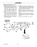
Страница 18: ...x bolt item 9 3 Figure 10 Secure all the way down the jam nut 3 4 NC item 15 on the 3 4 NC x 5 1 2 hex bolt item 9 4 Figure 10 Then bolt all this assembly into the long thread bushing of the rear lifting lever item 1 and adjust at the dimension as shown Secure the jam nut 3 4 NC item 15 with the rear lifting lever item 1 as shown in the figure 5 Figure 10 Insert the pivot spacer item 10 of the lif...

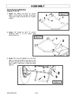
Страница 19: ...pring item 3 onto the longest side of the larch item 1 a 1 2 flat washer item 4 and secure with a 3 32 x 1 1 4 cotter pin item 5 2 Figure 12b Pivot the rear end of the front support item 1 and insert in the tractor frame The rear end of the front support will sit on the crossbar of the frame item 2 pull it forward and secure with three M16 x 60mm hex bolts item 3 5 8 flat washers item 4 three 16mm...

Страница 20: ...een the supports item 3 welded on the mower frame 5 Figure 15 Insert the ø7 16 x 9 13 16 lg deflector pivot pin item 1 through the support welded to the frame item 3 and the deflector assembly item 2 and a torsion spring item 4 The longest spring rod must go on the deflector assembly and the shortest one in the notch on the support welded on the frame item 3 6 Figure 15 Install a 7 16 flat washer ...

Страница 21: ...he anchor rod item 2 with two 1 NS nylon insert locknuts item 3 Tighten slightly 2 Figure 18 Install the front U anchor assembly item 1 to the mower front anchors item 2 3 Figure 19 Pull and slightly turn the latch item 2 Insert the anchor lever item 1 into the front supports item 3 Raise the anchor lever item 1 and lock it using the latch item 2 ...

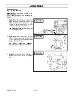
Страница 22: ...ch perpendicular as possible Align the tractor front wheels with the grip welded over the top mower deck It is important that the tractor is on four wheel drive mode 2 Figure 20B After climbing over the grip slowly continue advancing and climb on the belt guards Keep a constant speed and get down the mower The mower must be relatively centered between the tractor wheels 3 Figure 20C Stop the tract...

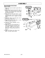
Страница 23: ...rious personal injuries This shaft turns at very high RPM If the collar is not locked to the shaft at tractor end or if the yoke at the mower end is not secured properly the driveline can fly loose with great force capable of causing serious injury or death Front Anchor Rod Installation figure 22 1 Figure 22 Pull out the latch item 3 until it completely goes out of the hole and rotate it slightly ...

Страница 24: ... goes out of the hole and rotate it slightly until the end is against the plate item 3 4 Figure 24 Remove the lifting arm item 2 from the two plates item 3 5 Figure 24 Rotate the latch item 1 until it enters the plates hole item 3 6 Repeat the same installation on the other lifting arm 7 Figure 25 Pull out the latch item 3 until it completely goes out of the hole and rotate it slightly until the e...

Страница 25: ...rding to conditions For maximum power run engine at or near full throttle Up and Down Control Refer to the tractor and or subframe operator s manual s for detailed hydraulic operation Engaging the Drive Mechanism Refer to the tractor s operating manual for instructions Transport Locking figure 26 The Transport Locking is to allow the use of the rear 3 point hitch without having the mower arms movi...

Страница 26: ...ear protective glasses and gloves when you manipulate the mower blades 1 Figure 27 Sharpen the blades with an angle grinder a file or an electric grinder It is important to keep the A angle when you sharpen the blades The edge of the sharp section of the blade must be of 1 64 0 40mm or less 2 BLADE BALANCING Figure 28 After sharpening the blades it is important to check they are still well balance...

Страница 27: ...the mower from the tractor according to the uninstallation step Turn over the mower to reach the blades 3 Figure 30 Place a wooden block item 2 between the blade item 1 and the mower frame to block the spindle from rotating during the removing of the blade bolts Move the wooden block with each blade removing NOTE You do not need the wooden block for the installation of the blades IMPORTANT Use goo...

Страница 28: ... routing it through the pulleys as shown on Figure 31b 5 Do the reverse step for reinstallation 6 The spring must be at 8 5 8 between the hooks as shown in Figure 31b 7 According to the belt supplier use a belt tension gauge Figure 31a Apply between 12 3 and 13 1 pound of force for a deflection of 68 11 16 on the longest section of a new belt between the right and left spindle 8 Figure 31 If the t...

Страница 29: ...t guard items 2 3 at an angle of 15 and pull them backward Put them aside for a future reinstallation 3 According to the belt supplier use a belt tension gauge Figure 32a Apply between 10 9 and 11 6 pound of force for a deflection of 68 11 16 on the longest section of the belt between the right and left spindle 4 Figure 32 If the tension of the belt is not as recommended untighten the 3 8 hex nut ...

Страница 30: ... height raise the mower to maximum 2 Figure 33 Remove the circle cotter item 2 and the 3 8 x 2 1 4 pin item 1 Adjust front wheel item 3 to the desired height Reinstall the pin and secure with the circle cotter item 2 3 Figure 33 Repeat the same steps for the three others front and rear wheels items 3 4 ...

Страница 31: ...te spindles driveshaft bearing wheels front wheel pivot mower lift kit Inspect mower blades and belt 40 hours Lubricate the cross and bearings 5 lever action pumps and telescoping member 8 10 lever action pumps with a quality lithium soap compatible E P grease meeting the N L G I 2 specification and containing no more than 1 molybdenum disulfide 100 hours Check gearbox oil level If necessary add I...

Страница 32: ...bove 65ºC 149ºF to avoid damages to the hydraulic components PROBLEM CAUSE CORRECTIVE MEASURE 1 Obstructed discharge Grass too wet Grass too long Cutting height too low Engine speed too low Moving speed too fast Wait for grass to get dry Raise the cutting height and mow twice Raise the cutting height Mow to maximum speed Slow down 2 Strips of uncut grass Moving speed too fast Engine speed too low ...

Страница 33: ...ping Obstructed mower frame Debris in the pulleys Worn out belt Unblock and clean up the mower frame Clean up pulleys Replace belt 6 Excessive vibration Debris over the mower frame or in the pulleys Damaged belt Damaged pulleys Pulleys not aligned Unbalanced blades Clean up the mower frame and the pulleys Replace belt Replace pulleys See your dealer Balance the blades 7 Mower loads the machine too...

Страница 34: ...are dull or worn Blades are damaged Deck in clogged with grass clippings Deck shell is damaged Mower spindle is bent or loosed Blades are installed incorrectly Level the deck correctly Sharpen or replace the blades Replace the blades Clean out the deck Repair or replace the deck Repair or replace the spindle Reinstall the blades correctly 11 SCALPING Scalping is when the mower deck comes close to ...

Страница 35: ...TD 6 BER0900003 5 Lockwasher 3 8 PTD 6 BER1200004 6 Flat washer 3 8 7 16 int PTD 6 BER1400004 7 Anti scalp roller 2 1 2 x 6 9 16 hole 2 BER3800075 8 Roll pivot pin 1 2 x 12 5 16 lg PTD 1 BER669914 9 Spacer bushing PTD 2 BER669916 10 Flat washer 1 2 9 16 int PTD 6 BER1400006 11 Cotter pin 3 32 x 3 4 lg 2 BER1500003 12 Bolt hex 1 2 NC x 7 1 2 lg PTD 1 BER0100085 13 Nylon insert locknut 1 2 NC PTD 1 ...

Страница 36: ...69 9 Rear wheel 6 x 2 assembly 2 BER671083 10 Latch 2 BER669894 11 Compression spring 0 906 x 4 1 4 x 0 050 wire 2 BER2200024 12 Flat washer 1 2 9 16 int PTD 2 BER1400006 13 Cotter pin 3 32 x 1 1 4 lg PTD 2 BER1500003 14 Footstep 1 BER672147 15 Button head cap screw 3 8 NC x 3 4 Gr 5 PTD 2 BER0800064 16 Lockwasher 3 8 PTD 6 BER1200004 17 Flat washer 3 8 7 16 int PTD 6 BER1400004 18 Plastic wear pl...

Страница 37: ...PARTS OM 0471MW A 35 UPPER PART OF MOWER FRAME ...

Страница 38: ...5 8 11 16 int PTD 3 BER1400008 12 Hex bolt M14 x 1 50 x 60mm PTD 4 BER0200043 13 Lockwasher 14mm PTD 10 BER1200014 14 Flat washer 14mm 15mm int PTD 4 BER1400024 15 Front anchor U 1 BER669982 16 Nylon insert locknut 1 14NS PTD 2 BER1000016 17 Right middle support 1 BER672708 18 Left middle support 1 BER672709 19 Hex bolt M14 x 2 00 x 60mm Gr 10 9 PTD 4 BER0200141 20 Hex bolt M14 x 2 00 x 70mm Gr 10...

Страница 39: ...PARTS OM 0471MW A 37 FRONT HITCH COMPONENTS ...

Страница 40: ...e spring 2 BER2200054 13 Right 3 point lifting pivot 1 BER672712 14 Left 3 point lifting pivot 1 BER672713 15 3 point Pivot pin PTD 2 BER669992 16 Flat washer 7 8 15 16 int PTD 2 BER1400012 17 Pin ø1 2 x 1 1 4 PTD 2 BER672118 18 Hairpin 2 5mm x 40mm 2 BER1800001 19 Circle cotter 1 1 8 PTD 2 BER1900010 20 Nylon lanyard 10 lg loop loop 2 BER4200053 21 Transport bracket 2 BER672110 22 Transport link ...

Страница 41: ...PARTS OM 0471MW A 39 REAR HITCH COMPONENTS ...

Страница 42: ... 18 Hex bolt 5 16 NC x 1 3 4 lg Gr 5 PTD 2 BER0100022 19 Driveline 1 BER4700335 20 Spring adjustment bracket 1 BER672163 21 Carriage bolt 5 8 NC x 2 1 2 PTD 1 BER0300041 22 Hex bolt 3 8 NC x 1 1 2 Gr 5 PTD 12 BER0100040 23 Stover nut 1 2 NC PTD 1 BER1100006 24 Flat washer 1 2 9 16 int PTD 2 BER1400006 25 Hex bolt 1 2 NC x 4 Gr 5 PTD 1 BER0100080 26 Belt 152 lg 1 BER4800049 27 Blade 23 3 BER5000016...

Страница 43: ...PARTS OM 0471MW A 41 DRIVE SYSTEM ...

Страница 44: ...1 BER2200026 6 Carriage bolt 3 8 NC x 1 1 4 lg Gr 5 PTD 6 BER0300009 7 Flat washer 13 32 ID x 1 1 2 OD PTD 6 BER1400041 8 Nylon insert locknut 3 8 NC PTD 6 BER1000006 9 Circle cotter 1 1 8 OD x 0 072 dia wire 2 BER1900010 10 Flat washer 1 2 9 16 int PTD 2 BER1400006 11 Rubber damper SBR ø7 8 x 13 32 2 BER4200064 12 Allen button head cap screw 8 32 x 3 4 PTD 2 BER0800063 13 Flat washer 8 3 16 int 2...

Страница 45: ...hick for 1 shaft 2 BER655087 7 Bolt hex 1 2 NC x 5 lg PTD 2 BER0100082 8 Flat washer 1 2 9 16 int PTD 4 BER1400006 9 Flat washer 3 4 13 16 int PTD 4 BER1400010 10 Stover lock nut 1 2 NC PTD 4 BER1100006 11 Flat washer 1 1 1 16 int PTD 2 BER1400029 12 Grease fitting 1 4NF 2 BER654106 13 Rear welded wheel support 2 BER669895 14 Phenolic wheel 6 x 2 ass y 2 BER3800076 15 Wheel bushing PTD 2 BER669891...

Страница 46: ...ER4300095 3 Bearing 6305_rs1 1 BER4300096 4 Lockwasher mb 5 1 BER4300097 5 Nut M25 x 1 5 km 5 1 BER4300098 6 Spindle hub 1 BER5000018 7 Round end key 8 x 7 x 25 1 BER5000019 8 Grease fitting M8 x 1 0 1 BER5000020 9 Spindle shaft 1 BER5000021 10 Spacer for bearing 1 BER5000022 11 Plug allen 1 8 NPT PTD 1 BER656090 12 Spindle 1 BER5000017 ...

Страница 47: ...5 3 Clamp yoke 1 15 splines 1 BER4700339 4 Journal cross kit 6E 3 BER4700130 5 Female driveline and Quick disconnect yoke 1 15 splines 1 BER4700337 6 Female shaft 1 15 splines and yoke 1 BER4700338 7 Quick disconnect yoke 1 15 splines 6E series 1 BER4700232 8 Spring lock repair kit 1 BER658113 9 Center housing 50 CV 1 BER658514 Repair kit 50 CV seal and liner 1 BER663632 ...

Страница 48: ... BER672125 3 Front push bar for mower 1 BER672728 4 Rear push bar for mower 1 BER672729 5 Bolt hex M12 x 1 75 x 30mm Gr 10 9 PTD 2 BER0200139 6 Lockwasher 12mm PTD 2 BER1200019 7 Flat washer 12mm PTD 2 BER1400030 8 Bolt hex M14 x 2 00 x 40mm Gr 8 8 PTD 4 BER0200080 9 Bolt hex M14 x 2 00 x 55mm Gr 8 8 PTD 2 BER0200135 10 Lockwasher 14mm PTD 6 BER1200014 ...

Страница 49: ...145 105 200 150 9 16 12NC 95 70 150 110 210 155 M14 X 1 5 99 73 155 115 215 160 9 16 18NF 105 79 165 120 235 170 M16 X 2 145 105 225 165 315 230 5 8 11NC 130 97 205 150 285 210 M16 X 1 5 155 115 240 180 335 245 5 8 18NF 150 110 230 170 325 240 M18 X 2 5 195 145 310 230 405 300 3 4 10NC 235 170 360 265 510 375 M18 X 1 5 220 165 350 260 485 355 3 4 16NF 260 190 405 295 570 420 M20 X 2 5 280 205 440 ...

Страница 50: ......

Страница 51: ... ...

Страница 52: ...roperty of those respective companies CNH Industrial America LLC reserves the right to make improvements in design and changes in specifications at any time without notice and without incurring any obligation to install them on units previously sold Specifications descriptions and illustrative material herein are as accurate as known at time of publication but are subject to change without notice ...

Отзывы: