ASSEMBLY
OM 0471MW-A
[16]
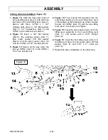
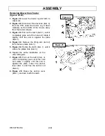
Lifting Arms Installation
(figure 10)
1. Figure 10:
Align the three last holes of
the rear lifting lever (item 1) with the three
last holes of the front lifting lever (item 2).
Secure with three 1/2"NC x 1 3/4"
carriage bolts (item 3), 1/2" flat washers
(item 4), 1/2" lockwashers (item 5) and
1/2"NC nylon insert locknuts (item 6).
2. Figure 10
Insert a 3/4" flat washer
(item 8), the urethane spring (item 7),
then insert another 3/4" flat washer
(item 8) and the pivot spacer (item 10)
onto the 3/4"NC x 5 1/2" hex bolt (item 9).
3. Figure 10
Secure all the way down the
jam nut 3/4"NC (item 15) on the 3/4"NC x
5 1/2" hex bolt (item 9).
4. Figure 10:
Then bolt all this assembly into the
long thread bushing of the rear lifting lever (item
1) and adjust at the dimension as shown. Secure
the jam nut 3/4"NC (item 15) with the rear lifting
lever (item 1) as shown in the figure.
5. Figure 10:
Insert the pivot spacer (item 10) of the
lifting lever assembly in the 3-point lifting pivot
(item 11) and secure with a 5/16" linchpin
(item 12).
6. Figure 10:
Insert the front lifting lever (item 2) in
the lifting arm (item 13) and secure with a 3/4" flat
washer (item 8) and 3/16" x 2" cotter pin
(item 14).
7.
Repeat the same installation on the other side.
Figure 10
Содержание 266WMM
Страница 9: ...GENERAL SAFETY INFORMATION OM 0471MW A 7 ...
Страница 10: ...GENERAL SAFETY INFORMATION OM 0471MW A 8 1 Safety stand 2 Secure point for safety stand ...
Страница 12: ...SAFETY LABELS OM 0471MW A 10 Replace immediately if damaged ...
Страница 37: ...PARTS OM 0471MW A 35 UPPER PART OF MOWER FRAME ...
Страница 39: ...PARTS OM 0471MW A 37 FRONT HITCH COMPONENTS ...
Страница 41: ...PARTS OM 0471MW A 39 REAR HITCH COMPONENTS ...
Страница 43: ...PARTS OM 0471MW A 41 DRIVE SYSTEM ...
Страница 50: ......
Страница 51: ... ...


