16
Figure 13. Example physical layout of mirrors and cameras for GuideStar II
system.
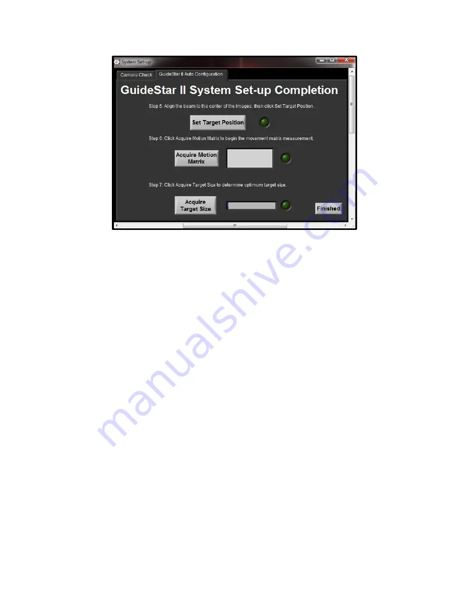
In Step 5, you will set the target position. To do this, click the Set Target Position
button. This will ensure that the system will return to the original alignment after
the motion acquisition. Once the Target Position has been set, the green light next
to the Set Target Position button will be lit. The target position can easily be re-
set later if additional adjustment is desired. This is done by re-clicking the Set
Target Position button.
In Step 6, you acquire the Motion Matrix. Click the “Acquire Motion Matrix”
button. Over the next several minutes, the system will move each motor (X1, Y1,
X2, Y2) by pre-defined amounts in the positive and negative directions and stop
once it has gathered enough information or the beam has moved to the edge of the
optical aperture. Once the Motion Matrix has been acquired, the green light next
to the Acquire Motion Matrix button will be lit.
In Step 7, you acquire the target size. Click the “Acquire Target Size” button and
the software will analyze the noise of the beam to determine a recommended
target size for the motion settings. (The recommended target size can be changed
later if desired.) Click the Finished button to close the System Set-up window and
save the settings via the subsequent pop-up window.
4.4.2
Guide Star II Tab
The first tab of the GuideStar II program is labeled Guide Star II. On this tab is
each camera’s image; a display of the target and centroid locations for each
Содержание 8783 GuideStar
Страница 1: ...User s Manual 8783 GuideStarTM II Controller ...
Страница 38: ......
Страница 39: ......


