


NEUTON
Corded Blower/Vacuum
-
Safety & Operating Instructions
5
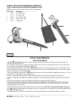
2. Orient the Collector Bag Tube with the Output Nozzle of the
Motor Housing as shown in
Figure 5
. Align the Posts on the
inside of the Bag Tube with the Grooves in the Output Nozzle.
Slide them together and twist the Bag Tube clockwise about
1/8th of a turn locking them together.
3. Hold open the spring loaded Vacuum Inlet Cover and align the
Grooves in the Upper Tube with the Posts on the inside of
Vacuum Opening (
Figure 6
). Slide the Upper Tube in the
opening and twist the Tube, using the Handle, clockwise about
1/8th of a turn locking them together.
TIP:
For ease of insertion, stand the Motor Housing on the Handle
and prop it up with your feet.
Chapter 3: Operating Your NEUTON Corded Blower/Vacuum
Starting and Stopping the Blower/Vacuum
•
Starting, stopping, and restarting an electric Motor repeatedly within a few seconds can generate a great deal of heat and damage the
Motor. To protect the life of your NEUTON Corded Blower/Vacuum, always wait at least five (5) seconds after stopping before restarting
the Blower/Vacuum.
•
Avoid collisions with hard objects, which could damage the Blower/Vacuum Tubes.
1. Perform the Daily Checks listed on the back cover of this
manual.
2. Connect the Blower/Vacuum to a working 120V outlet using a
heavy-duty outdoor extension power cord. Make a loop in the
power cord and push it through the hole in the Housing and
around the Cord Relief Hook (
Figure 7
) then plug it into the
Power Receptacle on the Blower/Vacuum.
3. While firmly grasping the Handle, push the ON/OFF Switch
(
Figure 7
)
to the ON Position (1). If the Blower/Vacuum does
not start, make sure you plugged the power cord into a live
120V outlet (simply use a lamp to check the power outlet) and
firmly plugged the power cord into the Blower/Vacuum Power
Receptacle. You can now adjust the speed of the Motor from
position 1 (lowest speed) to position 6 (highest speed) using
the Speed Adjust Switch (
Figure 7
).
4. To stop the Blower/Vacuum, move the ON/OFF Switch to the
(O) Position (
Figure 7
).
Groove
Figure 5
Post inside Tube
Post inside opening
Groove
Upper Tube Handle
Vacuum
Inlet
Cover
Figure 6
Figure 7
ON/OFF
Switch
Speed
Adjust
Cord Relief Hook
Cord Loop thru here


