background image

NTI AUDIO/HD VIDEO MATRIX SWITCH 


28

 
The output selection at the top of the page can be changed to any output to display the Scan Sequence Input selections and dwell 
times for that output.     
 
The inputs and the amount of time that each will be viewed (0-32000 seconds) can be set to cycle sequentially for each connected 
output.   If an input is set to 0 seconds, the sequence status will display “OFF”, and the input will be omitted from the scanning 
sequence.    To include an input in the sequence, enter a dwell time period from 1-32000 seconds, and press 

Apply

.  

 
To quickly clear all dwell time settings, press the 

Clear All

 button at the bottom of the page. All sequence settings will change to 

“OFF” and all dwell time settings will change to 0.      
 
To enable the scanning sequence for the output shown, place a checkmark in the “Sequence Enable” block.    

 
Tip: To quickly enable the scan sequence for multiple outputs, use the “Sequence Enable” blocks found on the Switch 
Page (page 23).  


Note: If only 1 input is set to Sequence “ON”, then the output connection to that input will not change when the Scanning 
Sequence is enabled.       


Note:  If the scanning sequence for an output is enabled through the web interface, then the Scan Mode for that output 

as configured through the LCD menu (page 9) will be disabled.   


Example of using Outputs Scanning Sequences 


Problem

:   A synchronous scan is desired for all outputs with a dwell time of 30 minutes per input, and no two outputs should be 

looking at the same input at any given time. 
 

Solution


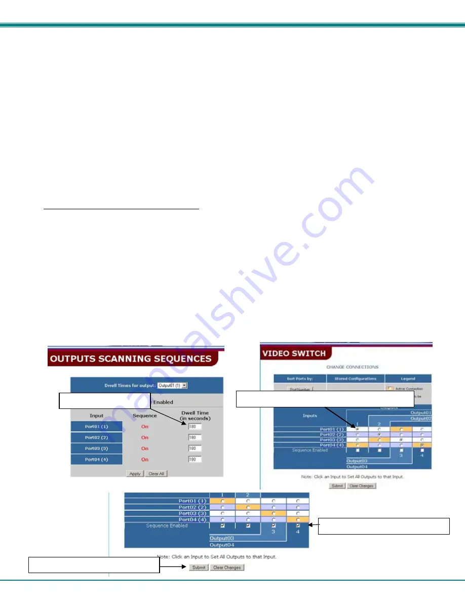
1.  Set the dwell time for all inputs listed in each output at 180 seconds (30 minutes).   Press “Apply”.  
2.  Go to the Video Switch page (page 23) and set each output to an input of the same number (1 to 1, 2 to 2, 3 to 3, etc..). 
      Click on “Submit” at the bottom of the Video Switch Page to submit selections and establish a connection and starting   
      point for the scanning sequence.   (Blocks shown in yellow in the third image indicate connections made.) 
3.  Click on the “Sequence Enable” box for each output  (from the Video Switch Page).   
4.  Click on “Submit” again to begin the scanning sequence for each output.      

 
From the moment the configuration is submitted,  a synchronous scan will begin on all outputs.   Each output will connect to its 
respective input for 30 minutes.    After 30 minutes, the outputs will each switch to the next consecutive input and remain 
connected for 30 minutes.   This cycle will continue indefinitely until sequencing is disabled.   
                    

Step 1- setup dwell times 

Step 2- setup starting point for scan and click “Submit” 

Step 3- enable the scanning sequence 

Step 4- Click on “Submit” to begin 

Содержание VEEMUX SM-8X4-HDA

Страница 1: ...MAN066 Rev Date 5 19 2008 SM 8X4 HDA Audio HD Video Matrix Switch Installation and Operation Manual VEEMUX Series...

Страница 2: ...rm or by any means electronic mechanical photocopying recording or otherwise without the prior written consent of Network Technologies Inc 1275 Danner Drive Aurora Ohio 44202 CHANGES The material in t...

Страница 3: ...erations 14 Setup Options 14 Ethernet Control 14 Telnet Interface Port 2000 14 Telnet Interface Port 2005 16 Command Summary 16 Command Detail 17 RU Read Unit Size 17 RO Read Connection for Output Por...

Страница 4: ...ect sources to the VEEMUX A 3 Figure 2 Stereo audio connection block 4 Figure 3 Connect devices audio and video 4 Figure 4 Connect cable for RS232 control 5 Figure 5 Connect the VEEMUX A to the Ethern...

Страница 5: ...ttons or optional IR remote Optional Feature Infrared Control see page 32 to order add IR to the part number i e SM 8X4 HDA IR Materials Materials Supplied with this kit NTI SM 8X4 HDA Audio HD Video...

Страница 6: ...nals from analog audio sources 10 OUTPUT BNC connectors for video and digital audio output to audio video devices 11 OUTPUT terminals for analog balanced or unbalanced stereo audio signal output to an...

Страница 7: ...able connection A terminal block for the connection of a line level stereo audio cable is located below each connector group See Fig 1 The VEEMUX A supports balanced line level audio signals as well a...

Страница 8: ...bles 2 Connect each digital audio device to an OUTPUT connector labeled DIGITAL If the audio device is a stereo type device connect it to an OUTPUT terminal block Connections to the terminal block sho...

Страница 9: ...5 INPUT 6 Pr Y Pb R G B O Digital Audio 6 5 R L R L Pr Y Pb O R G B Digital Audio INPUT 3 INPUT 4 Pr Y Pb R G B O Digital Audio 4 3 R L R L Pr Y Pb O R G B Digital Audio INPUT 1 INPUT 2 Pr Y Pb R G B...

Страница 10: ...RNET Pr Y Pb O R G B Digital Audio R INPUT 7 INPUT 8 Pr Y Pb R G B O Digital Audio L 8 R 7 L Pr Y Pb O R G B Digital Audio INPUT 5 INPUT 6 Pr Y Pb R G B O Digital Audio 6 5 R L R L Pr Y Pb O R G B Dig...

Страница 11: ...2 to source 2 monitor 3 to source 3 etc Along with the routing of the inputs video sources to the outputs monitors the keypad and LCD allow the users to configure the RS232 control interface The keypa...

Страница 12: ...ions To restore connections from memory use the following command IN Memory location ENTER Ex IN 5 ENTER Note If the current switch configuration includes assigned Scan Mode dwell time values pg 9 to...

Страница 13: ...CD Press MENU the following lines will be displayed 1 Set Baud Rate 2 Set Unit Addr Press MENU again the following line will be displayed 3 Set Scan Mode Press 3 to select that menu item The following...

Страница 14: ...ts use NTI Matrix Y 1 Y cables except for the last unit connected see Fig 6 For a pinout of the Matrix Y 1 cable see page 40 For straight through cable pinouts applicable to various terminal types see...

Страница 15: ...if the port is UNMUTED MU is 01 if the port is MUTED VV is a value between 00 to 99 see chart page 12 CC SW MM CR MM CR Save Matrix Connections Into Memory Bank xx Xx 00 09 RC SW LL CR LL CR Restore...

Страница 16: ...command as listed above or SW field is different from the serial address programmed in the switch memory the command will be ignored If the SW field corresponds to the serial address but the syntax is...

Страница 17: ...y Selection Description 1 Connect Video Output User to an Input CPU connect an output to an input 2 Connect All Video Outputs Users to an Input CPU connect all outputs to an input 3 Connect Audio Outp...

Страница 18: ...al port is displayed in parentheses 2 Select Baud rate current 9600 select PC serial port baud rate the current baud rate is displayed in parentheses 3 Set unit Address current 1 select the unit addre...

Страница 19: ...VV CR Read mute volume for output nn MU is 00 if the port is UNMUTED MU is 01 if the port is MUTED VV is a value between 00 to 99 see chart page 12 Ss nn dwt CR Set value of Scan Mode dwell time see p...

Страница 20: ...status mode SS 00 CR CR Disable auto status mode SX CR See details Examine connections AO OP CR ac OP IP CR Read audio connection for OP AS OP IP CR CR Connect audio OP to IP AA IP CR CR Connect all a...

Страница 21: ...Byte 6 Byte 7 Byte 8 Byte 9 p 0x70 c 0x63 Space 0x20 Output 1st digit 0x30 0x32 Output 2nd digit 0x30 0x39 0x2C Input 1st digit 0x30 0x32 Input 2nd digit 0x30 0x39 CR 0x0D This command will read the...

Страница 22: ...0x63 Space 0x20 Output 1st digit 0x30 0x32 Output 2nd digit 0x30 0x39 0x3A Input 1st digit 0x30 0x32 Input 2nd digit 0x30 0x39 CR 0x0D SS_00 Disable Auto Status Mode Command Byte 1 Byte 2 Byte 3 Byte...

Страница 23: ...input port that is connected to that audio output port AS Connect Audio Output Port to Input Port Command Byte 1 Byte 2 Byte 3 Byte 4 Byte 5 Byte 6 Byte 7 Byte 8 Byte 9 A 0x41 S 0x53 Space 0x20 Outpu...

Страница 24: ...1 Byte 2 Byte 3 Byte 4 Byte 5 Byte 6 Byte 7 Byte 8 Byte 9 A 0x41 M 0x4D Space 0x20 Output 1st digit 0x30 0x32 Output 2nd digit 0x30 0x39 0x2C 0 0x30 Mute Status 0x30 or 0x31 CR 0x0D Response Byte 1 B...

Страница 25: ...se Byte 1 Byte 2 Byte 3 Byte 4 Byte 5 Byte 6 Byte 7 Byte 8 Byte 9 a 0x61 r 0x72 Space 0x20 Output 1st digit 0x30 0x32 Output 2nd digit 0x30 0x39 0x2C 0 0x30 Mute Status 0x30 or 0x31 0x2C Byte 10 Byte...

Страница 26: ...rowser Address To open an SSL encrypted connection type Address You will be prompted to accept a certificate Accept the NTI certificate A Welcome Page will appear Figure 8 Web interface Welcome page E...

Страница 27: ...list and press the Submit button Figure 10 Web interface Video Switch page Note If radio buttons are selected in addition to using the Set all Outputs to Input option the selections made by the Set a...

Страница 28: ...Audio Switch page below enables the user to control the audio connections independently of the video connections Audio Switch Page Using the same methods of control described for the Video Switch pag...

Страница 29: ...change will take a few seconds and automatically redirect the user to the IP address specified Note Since the webserver will be restarting all active connections will be logged out The Website Timeout...

Страница 30: ...dministrator to change the names of the video and audio input ports displayed on the Switch page To change an input port name enter the name of the port for the desired input port number and press Sav...

Страница 31: ...ge The Outputs Scanning Sequences page displays the configuration of an automatic switching sequence from input video source to input for each output monitor The page displays output number being conf...

Страница 32: ...hen the Scan Mode for that output as configured through the LCD menu page 9 will be disabled Example of using Outputs Scanning Sequences Problem A synchronous scan is desired for all outputs with a dw...

Страница 33: ...date is attempted using the wrong firmware for the section an error message will be received No update will occur 4 Wait for the following message to appear may take several minutes Upload Succeeded F...

Страница 34: ...interface Update Web Server Click on this selection to globally update the Web Server to any settings that have been changed though Telnet the RS232 interface or via the front panel of the VEEMUX A A...

Страница 35: ...ay the Device Discovery Tool page Note The Device Discovery Tool requires the Java Runtime Environment to operate A link to the web page from which it can be downloaded and installed is provided on th...

Страница 36: ...se specified by default all IRT enabled switches will be configured as switch 1 Materials included IRT 64X32 Infrared Remote Transmitter for video matrix switches 2 AA Cell Batteries installed Feature...

Страница 37: ...witch followed by the decimal point and an error signal EE The error signal will display because there is no number to be displayed A number key must always be pressed before a SYS IN or OUT key is pr...

Страница 38: ...larger than the maximum number of outputs the IRT is configured for then once the OUT key is pressed the LCD will display the current switch and the error signal EE Change Input Port Press the desire...

Страница 39: ...letter c will display 2 Enter the number of inputs or outputs As the digits are entered they will be displayed and the last one entered will blink Note Only the inputs OR the outputs may be configure...

Страница 40: ...et maximum operating range between the transmitter and the front of the NTI switch infrared receiver Note Line of sight between IRT and receiver must be unobstructed Select up to 16 outputs Select up...

Страница 41: ...t the null modem cable between the serial port on the PC and the RS232 port on the VEEMUX A 3 Use HyperTerminal to prepare to connect to the VEEMUX A using settings 9600 baud 8 N 1 no flow Make sure H...

Страница 42: ...EMUX A waits this is normal 7 Click Transfer Send File from the HyperTerminal menu bar 8 Select Xmodem from the Protocol drop down menu 9 Click Browse Go to the directory containing the firmware to lo...

Страница 43: ...nal Ready Output 7 CTS CB 106 Clear To Send Input 8 RTS CA 105 Request To Send Output 9 N a N a N a No connection Specifications for Straight Through Serial Cable for CPU connection VEEMUX A to PS2 or...

Страница 44: ...cure the NTI switch to the rack using four 10 32 screws supplied Be sure to tighten all mounting screws securely Do not block power supply vents in the NTI switch chassis if provided Be sure to enable...

Страница 45: ...gital Audio Signal Type S PDIF Connectors RCA Orange or BNC customer defined Input Impedance 75 ohms Output Impedance 75 ohms Resolution 16 to 24 bit Sampling Rate 32 to 96 kHz RS232 Control RS232 Con...

Страница 46: ...g These products have protective earth ground terminals and are built with full attention to consumer safety There must be an un interruptible safety earth ground between the main power source and the...

Страница 47: ...fety statements 43 Scan Mode 9 Scanning Sequences 28 serial cable 5 serial setup 27 Sertest 14 servicing 43 setup 15 Software control 17 Telnet 15 Telnet password 1 Telnet Port 2005 17 unit address 10...

Отзывы: