


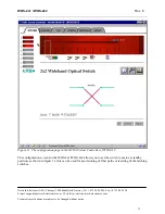


WOS-2x1 / WOS-2x2
Rev. 6
Network Electronics ASA, Thorøya, 3204 Sandefjord, Norway, Tel.:+47 33 48 99 99 Fax: +47 33 48 99 98
E-mail: [email protected] - Web: http://www.network-electronics.com
Technical specifications are subject to be changed without notice
8
4. Module status
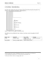
The status of the module can be monitored in four ways.
1. GPI at the rear of the sub-rack.
2. LEDs at the front of the sub-rack.
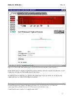
3. GYDA-SC controller.
4. Directly accessing the RS-422 bus.
Of these four, the GPI and the LEDs are mounted on the module itself, whereas the GYDA-SC controller
is a separate module giving access to remote monitoring of the status of the card through either a web
interface or SNMP. The functions of the GPI and the LEDs are described in sections 4.1 to 4.3.
The GYDA-SC controller is described in section 4.4. The commands the modules will respond to over the
RS-422 bus, can be found in section 4.5.
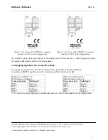
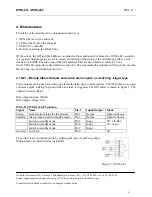
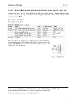
4.1 GPI – Module Status Outputs and switch alarm inputs, non-latching trigger type
These outputs can be used for wiring up alarms for third party control systems. The GPI output is an open
collector output, sinking to ground when an alarm is triggered. The GPI outlet is shown in figure 5. The
connector used is RJ-45.
Max output current: 100mA
Max output voltage: 30V
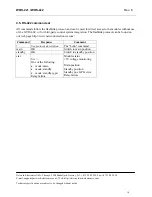
WOS-2x1/WOS-2x2 GPI pinning:
Signal Name
Pin
# Input/Output Mode
Status
General error status for the module
Pin 1
Output
Open Collector
Standby Alarm when switch in standby mode
Pin 2
Output
Open Collector
Switch to standby mode
Pin 5
Input
Switch to standby mode
Pin 6
Input
Switch to standby mode
Pin 7
Input
0V= standby
5V= main
Ground 0 volt pin
Pin 8
0V
The switch is set in standby mode by sinking pin5, pin6 or pin7 to ground.
Pin6 and pin7 are hardwired as logical OR.
Figure 5: GPI Outlet


