background image

SDI-TD-MUX-4 


Rev.8 


network-electronics.com | 18 

8 Laser safety precautions 

These are guidelines to limit hazards from laser exposure. 

All the available EO (including ETH100) units in the Flashlink range include a laser. 

Therefore this note on laser safety should be read thoroughly. 

The lasers emit light at wavelengths from 1270nm up to 1610nm. This means that the human 
eye cannot see the beam, and the blink reflex cannot protect the eye. (The human eye can 
see light between 400 nm to 700 nm). 

A laser beam can be harmful to the human eye (depending on laser power and exposure 
time). Therefore: 

Be careful when connecting / disconnecting fibre pigtails (ends).  

Never look directly into the pigtail of the laser/fibre.  


Never use microscopes, magnifying glasses or eye loupes to look into a fibre 
end. 

Use laser safety goggles blocking light at 1310 nm and at 1550 nm 

Instruments exist to verify light output power: Power meters, IR-cards etc. 

Flashlink features: 

All the laser module cards in the Flashlink product range, are Class 1 laser products 
according to IEC 825-1 1993, and class I according to 21 CFR 1040.10 when used in normal 
operation. 

More details can be found in the user manual for the FR-2RU-10-2 frame. 

Maximum output power

1

5 mW 

Operating wavelengths: 

> 1270 nm 


1

 Max power is for safety analysis only and does not represent device performance. 

Содержание SDI-TD-MUX-4 Flashlink

Страница 1: ...network electronics com 4 x SD SDI DVB ASI to HD SDI Time Division Multiplexer Rev 8 Flashlink User Manual SDI TD MUX 4 ...

Страница 2: ...1 10 Clarified max 35 Mbps active transport rate for DVB ASI 7 6 2008 11 04 Corrected GPI allocation GPI0 and GPI1 was swapped and GPI2 and GPI3 was also swapped 6 5 2008 04 08 Added text in chapter 1 3 unused input termination Added Declaration of Conformity 5 4 2007 10 29 New front page 4 3 2007 10 08 Added Materials Declaration and EFUP 3 2 2006 12 22 Moved Specifications chapter to chapter 2 2...

Страница 3: ... boards FW rev 2 0 and later 9 3 2 Older boards FW rev 1 x and 0 x 11 4 Operation 14 5 Front Panel LEDs 15 6 GPI alarms 16 6 1 GPI Data connections RJ45 16 7 GYDA SC Interface 17 8 Laser safety precautions 18 General environmental requirements for Network Electronics equipment 19 Product Warranty 20 Appendix A Materials declaration and recycling information 21 A 1 Materials declaration 21 A 2 Recy...

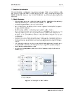
Страница 4: ...UX 4 Built in routing switcher for allocating input signals to output streams Four separate and independent streams in the output HD SDI output signal are used allowing uninterrupted signal transport of remaining signals on loss of input feed Separate stream clock reference data for each channel is transferred for remote clock regeneration Optical and electrical 1 485 Gbps HD output TDM signal Bot...

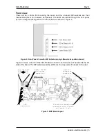
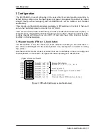
Страница 5: ...panel as shown in Figure 2 Figure 2 Front Panel View with LED Indicators only leftmost rack position shown Figure 3 shows a sketch of the SDI TD MUX 4 board The front view will be towards the left side of the board The DIP switches and the LED s are the only parts of interest for the user Figure 3 MUX Board Layout DIP switches OFF ON 0 1 Jumper needed for proper operation Optical backplane connect...

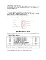
Страница 6: ...signals for driving external alarm devices Figure 4 Rear view showing the backplane Note that the same backplane can be used for both the SDI TD MUX 4 board and the SDI TD DMUX 4 board The following connectors are available Name Description Connector Type SD1 Input for 270 Mbps SD SDI or DVB ASI BNC SD2 Input for 270 Mbps SD SDI or DVB ASI BNC SD3 Input for 270 Mbps SD SDI or DVB ASI BNC SD4 Input...

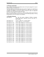
Страница 7: ... 13T 1310nm 7 5dBm laser electrical interface SDI TD MUX 4 15T 1550nm 0dBm laser electrical interface SDI TD MUX 4 C1270 1270nm 0dBm CWDM laser electrical interface SDI TD MUX 4 C1290 1290nm 0dBm CWDM laser electrical interface SDI TD MUX 4 C1310 1310nm 0dBm CWDM laser electrical interface SDI TD MUX 4 C1330 1330nm 0dBm CWDM laser electrical interface SDI TD MUX 4 C1350 1350nm 0dBm CWDM laser elec...

Страница 8: ...PTE 346M 2000 Transmission circuit fibre Single Mode Light source F P DFB laser Optical power 7 5dBM 1310nm F P laser 0 dBm DFB laser Optical centre wavelength 1310nm 1550nm CWDM according to ITU T G 694 2 Max wavelength drift 20nm F P lasers 6nm DFB lasers Jitter UI Unit Interval Max 0 2UI 1485Mbps Connector return loss better than 40dB w SM fibre Connector SC UPC Electrical Temperature range 0 t...

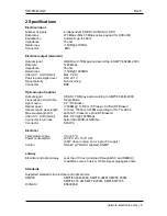
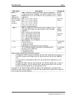
Страница 9: ...rmware revision FW 2 0 and later have more functions but less flexibility on channel swapping 3 1 Newer boards FW rev 2 0 and later The DIP switches control the channel to stream allocation according to the below table It also controls enable bypass for the cable equalisers See also Figure 5 for details on setting the switches Note that when GYDA SC mode is selected there are no limitations on how...

Страница 10: ... default See note below S S is not in use 0 spare not in use 1 spare not in use preferably leave the switch in the 0 position 0 is factory default O O is controlling whether the board is controlled by DIP switches or from GYDA SC 0 GYDA SC control 1 DIP switch control 0 is factory default Notes regarding distribution and cable equalisers Changing the RRR setting to something else than 000 duplicat...

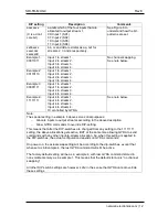
Страница 11: ...nged from last setting Default on power on is all active Cable Equalizers Can be turned on off from GYDA SC Factory default is enable Cable equaliser bypass enable according to DIP switches See above table Channel swap Can be controlled by GYDA SC all options available Channel swap distribution according to DIP switches See above table 3 2 Older boards FW rev 1 x and 0 x The DIP switches control t...

Страница 12: ...tream 3 Input 4 to stream 4 Or controlled by GYDA See note below Note The special setting in example 4 above serves dual purposes Allocate inputs to output streams according to the above description Allow GYDA commands to override DIP setting This means that after the DIP switches are changed from any setting to the 11111111 setting the above allocations gets active BUT at the same time allowing G...

Страница 13: ...g still active on the MUX board on errors but without any functional significance EDH flags Can be read from GYDA Flags still operating on board but without any functional significance EDH masks Can be changed from GYDA Not stored in non volatile memory so power on default is all active until GYDA configures otherwise EDH masks remains unchanged from last setting Default on power on is all active ...

Страница 14: ...ace according to SMPTE 346M 2000 An SDI TD DMUX 4 board is required to reconstruct the four 270 Mbps signals normally at a remote location and linked via an optical fibre or an electrical coax cable Channel swapping is available either from DIP switches or remotely via the standard GYDA SC interface All inputs can be either 270 Mbps SD SDI or DVB ASI 188 or 204 word packets ...

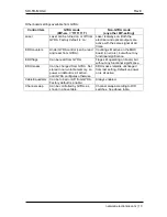
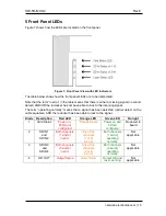
Страница 15: ... a signal has been detected carrier detect on the cable equaliser AND the reclocker has been able to lock to the signal Diode Description Red LED Orange LED Green LED No light 1 Card Status Power on FPGA not configured Not applicable Power on and FPGA configured No power to board 2 SD IN 1 and SD IN 2 Both channels 1 and 2 in error One of the channels 1 or 2 in error Both channels 1 and 2 operatin...

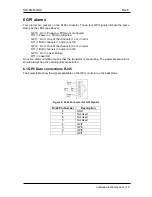
Страница 16: ...nd 2 are OK GPI2 On One of the channels 3 or 4 in error Off Both channels 3 and 4 are OK GPI3 On Laser Failure Off Laser OK An active alarm condition means that the transistor is conducting The power present alarm should always be active during normal operation 6 1 GPI Data connections RJ45 The below table show the signals available on the GPI connector on the backplane Figure 8 RJ45 Connector for...

Страница 17: ...n rack position 9 and a power supply unit in rack positions 10 and 11 For details on the GYDA SC graphical user interface or the communication protocol refer to the GYDA SC documents or contact our support department at support network electronics com For information on which parameters are controllable from GYDA SC refer to section 3 of this manual Figure 9 GYDA SC presentation of rack with an SD...

Страница 18: ...ure time Therefore Be careful when connecting disconnecting fibre pigtails ends Never look directly into the pigtail of the laser fibre Never use microscopes magnifying glasses or eye loupes to look into a fibre end Use laser safety goggles blocking light at 1310 nm and at 1550 nm Instruments exist to verify light output power Power meters IR cards etc Flashlink features All the laser module cards...

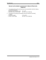
Страница 19: ...ranteed performance specification under the following environmental conditions Operating room temperature range 0 C to 45 C Operating relative humidity range up to 90 non condensing 2 The equipment will operate without damage under the following environmental conditions Temperature range 10 C to 55 C Relative humidity range up to 95 non condensing ...

Страница 20: ...Warranty The warranty terms and conditions for the product s covered by this manual follow the General Sales Conditions by Network Electronics ASA These conditions are available on the company web site of Network Electronics ASA www network electronics com ...

Страница 21: ...nt in SJ T11363 2006 X Indicates that this toxic or hazardous substance contained in at least one of the homogeneous materials used for this part is above the limit requirement in SJ T11363 2006 This is indicated by the product marking A 2 Recycling information Network Electronics provides assistance to customers and recyclers through our web site http www network electronics com Please contact Ne...

Страница 22: ... EEC EMC 2004 108 EEC HARMONISED STANDARDS applied in order to verify compliance with Directive s EN 55103 1 1996 EN 55103 2 1996 EN 60950 1 2006 TEST REPORTS ISSUED BY Notified Competent Body Report no Nemko E07381 00 TECHNICAL CONSTRUCTION FILE NO Not applicable YEAR WHICH THE CE MARK WAS AFFIXED 2008 TEST AUTHORIZED SIGNATORY MANUFACTURER AUTHORISED REPRESENTATIVE Established within EEA Date of...

Отзывы: