SDI-TD-MUX-4
Rev.8
network-electronics.com | 10
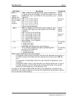
DIP setting
Description
Comments
RRR----1
(Dashes ‘-‘
indicate that
these switches
are not related
to this
function).
‘RRR’ (or RD0-2) are allowing remote control of distribution
on the receiver side. Preferably, use the DIP switches on the
DEMUX side only or use GYDA-SC, if so is possible in your
application.
000: 1=>1 2=>2 3=>3 4=>4
001: 1=>1 1=>2 3=>3 4=>4
010: 1=>1 1=>2 3=>3 3=>4
011: 1=>1 1=>2 1=>3 4=>4
1xx: 1=>1 1=>2 1=>3 1=>4
(Input to stream allocation)
‘000’ is
factory
default.
See note
below.
---EEE-1
‘EEE’ (or EQ0-2)are controlling the cable equalisers. Leave
in position ‘000’ unless you have reasons to turn off cable
equalisers.
000: 1=ena 2=ena 3=ena 4=ena
001: 1=byp 2=ena 3=ena 4=ena
010: 1=byp 2=byp 3=ena 4=ena
011: 1=byp 2=byp 3=byp 4=ena
1xx: 1=byp 2=byp 3=byp 4=byp
(byp = Bypass , ena = Enabled)
‘000’ is
factory
default.
See note
below.
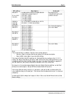
------S-
‘S’ is not in use.
0: spare (not in use)
1: spare (not in use)
(preferably, leave the switch in the ‘0’-position)
‘0’ is factory
default.
-------O
‘O’ is controlling whether the board is controlled by DIP-
switches or from GYDA-SC.
0: GYDA-SC control
1: DIP-switch control
‘0’ is factory
default.
Notes regarding distribution and cable equalisers:
−
Changing the ‘RRR’ setting to something else than ‘000’ duplicates input signals on
the HD mux-stream and thereby limits the signal options at the receiver (DEMUX)
side.
−
You may have to swap cables at the rear to get exactly the configuration you are
looking for.
−
Changing the ‘EEE’ setting to something else than ‘000’ will bypass one or more of
the cable equalisers. This will normally give reduced performance. Only use this
feature if you understand why you would want to do it.
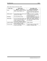
On power-on, the actual settings will be according to the dip-switches, except when the
GYDA-SC control mode is selected. In that case, the last GYDA-SC setting will be restored
from on-board non-volatile memory.


