


SDI-TD-DMUX-4
Rev.
5
1.2
Front view
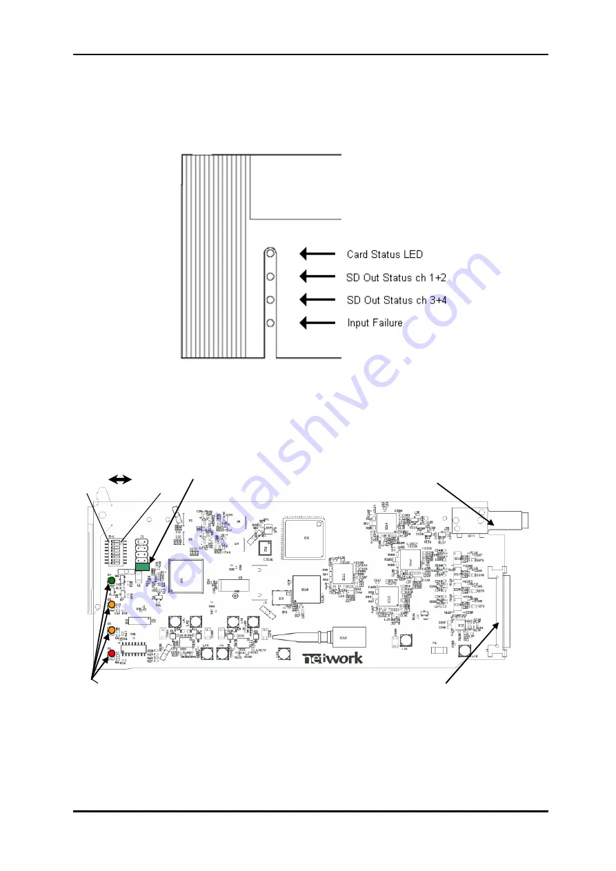
There will be a frame front covering the board and the on-board DIP-switches are then
inaccessible (the cover can be opened). The LEDs are visible through the front panel by use
of integral optical guides in the front panel, as shown in Figure 2.
Figure 2: Front Panel View with LED Indicators (only leftmost rack position shown)
Figure 3 shows a sketch of the SDI-TD-DMUX-4 board. The front view will be towards the
left side of the board. The DIP switches and the LEDs are the only parts of interest for the
user.
DIP switches
OFF ON
’0’ ’1’
Jumper needed
for proper
operation
Optical
backplane
connector
LED
indicators
Electrical backplane
connector with signals
and power lines
Figure 3: Demux Board Layout
network-electronics.com | 5


