background image

SDI-IP-GTW User Manual


27 

Main tab (page) 

Sub-tab 

Description 

this page. 

Network 

This is where IP address, subnet mask and default 
gateway is defined for management interface and 
data interface. In addition, for the data interfaces, the 
Advanced tab provides configuration of in-band 
management. The SFP tab provides information 
about the SFP. 

Time settings 

Set SNTP server address. Current time is shown if 
valid SNTP server is already defined. 

Alarms 

Provides a list of all alarms and configuration of 
severity level for the alarm events. 

SNMP 

A page to add snmp trap servers 

Ping 

A page offering an interface to check for connectivity 
by pinging a remote host. 

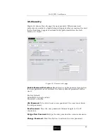
Security 

Enable/disable user login for GUI control. 

RIP-2 

RIP-2 is an option. This page allows configuration of 
the RIP messages. 


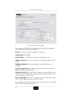
This is where each input is configured  

Main 

This is where the main parameters of each input is 
configured. In addition, status of each stream is 
shown. 

FEC 

This is where the FEC parameters are configured. 

IP TX 

VLAN 

This is where VLAN tagging is configured. 


This is where the outputs are configured. 

Main 

This is where the main parameters of the outputs are 
configured. 

FEC 

This is where the FEC parameters are configured. 

IP RX 

VLAN 

This is where VLAN tagging is configured. 

Network 


Overview of IP addresses UDP ports and bitrates. 

Save/Load 


Save and load of configurations. 


Select a page by pressing the tab of the page you want to view.  

In order to activate a change in a parameter, you need to press the 
Apply button. The refresh button, will read back all parameters on the 
page from the unit. 

3.4


Status  

Figure 8 shows the overall status of the unit. This view shows a unit in 
IP transmit mode. In this view a block diagram of the unit with SDI 
inputs and IP port is shown. The unit name and the mode are 
illustrated. The input is coloured depending on its status: red when not 
in sync, green when in sync and grey when the input is disabled from 
software. In the same way the IP port is coloured dependent on its 
status.  

Содержание SDI-IP-GTW

Страница 1: ...network electronics com SDI to IP Gateway Rev 1 3 0 Flashlink User Manual SDI IP GTW...

Страница 2: ...This page is intentionally left blank...

Страница 3: ...k Electronics If passing the equipment to a third party please ensure to pass all relevant documentation including this manual Issues of this manual are listed below Revision Date Software version Com...

Страница 4: ...SDI IP GTW User Manual 4 This page is intentionally left blank...

Страница 5: ...15 2 1 Introduction 15 2 1 1 Read this first 15 2 1 2 To inspect package content 15 2 2 Installing the Equipment 15 2 2 1 Selecting a site for the equipment 15 2 2 2 To fix the equipment 16 2 2 3 To c...

Страница 6: ...7 4 2 1 Introduction 57 4 2 2 IP Transmit Mode 57 4 2 3 IP Receive Mode 57 4 2 4 Management 58 4 2 5 Alarms 58 4 3 Overview of Video over IP 59 4 3 1 Protocol mapping 59 4 4 Data Flow Block Diagrams 6...

Страница 7: ...2 B 4 Alarm relay and maintenance port specification 72 B 5 AC Mains Input 72 B 6 Physical Details 72 B 7 Environmental Conditions 73 B 8 Compliance 73 Appendix C References 74 Appendix D Upgrade of F...

Страница 8: ...SDI IP GTW User Manual 8 This page is intentionally left blank...

Страница 9: ...ital Interface stream over an Ethernet IP link This manual provides necessary information for installation operation and day to day maintenance of the unit 1 1 2 Warnings Cautions and Notes 1 1 2 1 He...

Страница 10: ...mail support network electronics com Web http www network electronics com Service 47 90 60 99 99 Mailing and visiting address Network Electronics ASA Thor ya P O Box 1020 N 3204 Sandefjord Norway This...

Страница 11: ...deo signals to the IP based Network At the reception site the unit receives the IP encapsulated data end regenerates the SDI stream Figure 2 provides an overview of the SDI IP GTW in transmit and rece...

Страница 12: ...s LED is lit when power is being received by the unit Alarm Red This LED is lit when a failure is detected by the unit I e at least one alarm with severity level Critical is present IP TX Blue This LE...

Страница 13: ...d the data port 1 5 4 Construction The SDI IP GTW SDI to IP Video Gateway consists of a main board and an SDI board mounted horizontally in a screened cabinet The unit is 1RU high and two units can be...

Страница 14: ...ctionality enabled through software licenses Functionality Max value Description Forward Error Correction NA Pro MPEG Forward Error Correction enabled for use on the transmitted stream VLAN tagging NA...

Страница 15: ...nal accessories you may have ordered o SDI IP GTW o Power cord o User s manual 2 2 Installing the Equipment 2 2 1 Selecting a site for the equipment As with any electric device you should place the SD...

Страница 16: ...y that they are not likely to be walked on or pinched by items placed upon or against them Do not run ac power cables and signal cables in the same duct 2 2 4 Equipment access The SDI IP GTW has conne...

Страница 17: ...e operating ambient temperature Figure 4 shows the air path through the unit Figure 4 Air Path though the unit 2 2 6 To connect the equipment Once the SDI IP GTW is installed in its intended operating...

Страница 18: ...utput signal may be locked to this input reference signal 2 2 6 2 Ethernet data port Connect the Ethernet data port to the network In IP transmit mode the SDI IP GTW will send an IP stream to the netw...

Страница 19: ...the removed plug is inserted into a mains outlet Caution Power supply cords should be routed so that they are not likely to be walked on or pinched by items placed upon or against them paying particul...

Страница 20: ...ed use an M4x12mm long pozidriv panhead Using a longer screw may cause a safety hazard 2 3 2 3 Connecting the Video Gateway to the AC Power Supply Warning Do not overload wall outlets and extension co...

Страница 21: ...ecification Safety status SELV Type Analogue Connector name SDI IN SDI OUT Connector type BNC 75 ohm socket Signal Compliant with ANSI SMPTE 259M 1997 Line rate 270Mbit s 2 4 2 1 SDI input Inputs conn...

Страница 22: ...stomers to use different SFPs for special distance cost existing infrastructure and future expansion requirements The SDI IP GTW is prepared for electrical 1000Base T or optical 1000BASE SX and 1000BA...

Страница 23: ...ved by the unit Alarm Red This LED is lit when a failure is detected by the unit IP TX Blue This LED is lit when the unit is configured to transmit data to the IP Network IP RX Yellow This LED is lit...

Страница 24: ...talled in a suitable location The unit has been connect to external equipment as required 2 6 2 Powering Up To power up the unit by inserting the power cable connected to a power source The cooling fa...

Страница 25: ...wer installed on your computer this will be detected and you will be informed to install this prior to configuring the SDI IP GTW Note Network Electronics recommend using Internet Explorer 6 0 or newe...

Страница 26: ...TX IP RX Network and Save Load Some of the main pages have a number of sub pages The following table gives an overview of the different pages Main tab page Sub tab Description Status The current stat...

Страница 27: ...tion status of each stream is shown FEC This is where the FEC parameters are configured IP TX VLAN This is where VLAN tagging is configured This is where the outputs are configured Main This is where...

Страница 28: ...vent This can be Critical or Warning Text This gives a description of the alarm condition Source This parameter describes which module has created the alarm Alarm ID Each alarm condition has an alarm...

Страница 29: ...first time the alarm log page is visited the alarm log is read from the unit In order to refresh the alarm page press the Refresh button Note The alarm log is not automatically refreshed when you visi...

Страница 30: ...it Software build time The time and date when the software was compiled Internal temperature The internal temperature of the unit shown in degrees Celsius and Fahrenheit Flash Power LED When this butt...

Страница 31: ...by decimal points full stop period e g 255 255 255 0 MAC address The MAC address is displayed For the Data interface the following is also possible to configure the following on the main tab Media se...

Страница 32: ...use the data port as the default management interface This should be enabled to allow remote configuration of the unit through data port when the client is connected to other LANs Multicast router The...

Страница 33: ...SDI IP GTW User Manual 33 Figure 12 The device info network and advanced sub page IP RX 3 5 1 2 SFP Figure 13 The device info page Network and SFP sub page...

Страница 34: ...5 2 Time setting Figure 14 shows the sub page for time setting used for alarm reports Figure 14 Time setting sub page Current time This shows the current time used by the unit SNTP server address The...

Страница 35: ...l Filtered Warning or Critical from the list and press Apply Filter Change to change the severity level The severity level is reflected in the user interface and in the SNMP traps sent by the unit The...

Страница 36: ...Destination Servers List of IP addresses to added trap servers Add Trap Server Enter the IP address of the server and press the Add Trap Server button Delete a trap server Select the IP address in the...

Страница 37: ...etween data interfaces the allow ping response option on the network page advanced tab see ch 3 5 1 must be enabled on both the transmitter and the receiver TTL Time to live Enter the time to live val...

Страница 38: ...he number of ping requests that were not answered If the timeout counter is incrementing while the OK responses counter is zero there is no contact with the specified IP address Last The round trip ti...

Страница 39: ...e Enable Password Protection Mark this to enable password protection If a new password is not entered the factory default password will be used Factory default Administrator login admin Password salva...

Страница 40: ...the lowest metric i e in effect automatic redundancy switchover Figure 19 RIP 2 sub page The configuration parameters are as follows Mode Controls the mode of the RIP 2 engine The valid choices are O...

Страница 41: ...rom a Critical Clear change to when the clear metric value will be sent in the outgoing RIP 2 messages In other words it specifies the time that must elapse in alarm OK state before the SDI IP GTW act...

Страница 42: ...Input Configuration Enable input Tick this box to enable an input If this is not ticked you will not receive any SDI stream in this input The input port will be grey in the status view See Section 3...

Страница 43: ...rt and four higher than the media port e g if UDP destination port is 5510 column FEC UDP port is 5512 and row FEC UDP port is 5514 UDP source port Enter the UDP source port to be used in the outgoing...

Страница 44: ...Status Resolved Yes when the MAC address of the receiving unit is found The parameter is always yes when multicast is used No when the MAC address is not found Destination MAC address Shows the destin...

Страница 45: ...protecting it It is recommended to enable skew but this may cause incompatibility problems with other manufacturers equipment FEC overhead This number is the overhead in percent caused by the current...

Страница 46: ...ber of frames discarded at the output of the unit 3 6 3 VLAN Settings Figure 22 The VLAN page of an IP transmitter This sub page will only appear if the unit is enabled with VLAN tagging By enabling V...

Страница 47: ...ht of the page is related to the selected stream 3 7 1 1 Output Configuration Enable output Tick this box to enable the SDI output If this is not ticked you will not send any SDI stream on this output...

Страница 48: ...peated e g frozen picture until the data is back again This number may therefore be high dependent on the duration of the data loss 3 7 1 3 Reference Signal This frame contains status information for...

Страница 49: ...rors A counter showing the number of RTP sequence errors caused by lost packets or out of order packets A value of zero indicates that all packets are received in order Lost IP frames A counter showin...

Страница 50: ...ed Max burst loss length Maximum number of IP frames in a burst loss Columns L This shows the number of columns in the incoming FEC stream Rows D This shows the number of rows in the incoming FEC stre...

Страница 51: ...pear if the unit is enabled with VLAN Enable VLAN tagging Tick this box to enable the use of VLAN tagging VLAN ID Enter the ID of the VLAN 3 8 Network Figure 26 shows the Network page for a unit confi...

Страница 52: ...mes received over the network data interface Total TX bitrate The total bitrate of IP frames sent over the network data interface TX load The percentage of the total interface speed used by the IP fra...

Страница 53: ...of a unit configured in IP RX mode shows information summary for the SDI output For the SDI output the table shows the name of the output if the output is enabled Yes No the IP source address the UDP...

Страница 54: ...erating is called the current configuration 3 9 1 Saving a Configuration In order to save the current configuration of the unit to a file press right mousebutton on the link labelled XML Configuration...

Страница 55: ...onfiguration In order to upload a new configuration file to the unit browse to find the file and select the file or enter the file including path directly When the file name including path is entered...

Страница 56: ...SDI IP GTW User Manual 56 This page is intentionally left blank...

Страница 57: ...The SDI IP GTW is able to handle SDI signals on the following formats ANSI SMPTE 259M 1997 The sourced SDI stream is then processed by the Main board The SDI IP GTW will encapsulate the SDI data acco...

Страница 58: ...Alarm LED on the front and on the rear SNMP traps to Network Management System Alarm relay The user can define the severity level of the different alarm events The three levels are No alarm Warning an...

Страница 59: ...m One or more SDI frames have been repeated at the SDI output Typical cause is either data loss at the input or too low buffer fullness when using lock to reference 172 No SDI reference sync Critical...

Страница 60: ...HTTP is used when the unit is configured and monitored via the internal WEB server SNMP is used for alarm traps and simple status polling Telnet is used for development purposes The transport stream d...

Страница 61: ...SDI IP GTW User Manual 61 Figure 31 Data flow between two units...

Страница 62: ...SDI IP GTW User Manual 62 This page is intentionally left blank...

Страница 63: ...with a mixture of mild detergent and water Make sure that the unit is completely dry before reconnecting it to a power source 5 2 3 Servicing Warning Do not attempt to service this product as opening...

Страница 64: ...ve the covers of this equipment Hazardous voltages are present within this equipment and may be exposed if the covers are removed Only Network Electronics trained and approved service engineers are pe...

Страница 65: ...sult of action is Yes If the result of action is No 1 Check the Power LED Is the Video Gateway still working If the Video Gateway is clearly working normally then the Power LED itself is probably at f...

Страница 66: ...ng of this Equipment 5 5 1 General Dispose this equipment safely at the end of its life time Local codes and or environmental restrictions may affect its disposal Regulations policies and or environme...

Страница 67: ...ynchronous Serial Interface A common physical interface for transmission of MPEG2 Transport Streams i e MPEG2 compressed video over a serial interface typically coaxial cables DWDM Dense Wavelength Di...

Страница 68: ...i Program Transport Streams Transport Streams that carry multiple TV Radio services Multicast An IP mechanism that allows transmission of data to multiple receivers A multicast can also have several t...

Страница 69: ...asts in a network SDP is used as a mechanism to describe an ongoing multicast for example the type of compression used IP addresses etc SDTI Serial Data Transport Interface A mechanism that allows tra...

Страница 70: ...The common name for MPEG2 Transport Streams A bit stream used to carry packets with MPEG 2 compressed video A transport stream typically carries approximately 10 compressed TV channels but can consis...

Страница 71: ...Link layer VLAN Transport layer UDP RTP FEC DVB MPEG 2 IEEE Std 802 3 2002 IEEE Std 802 1q RFC 760 RFC 768 RFC 1889 RFC 3550 RFC 2250 Pro MPEG CoP3 rev 2 RFC2733 Pro MPEG CoP3 rev 2 ISO IEC 13818 1 20...

Страница 72: ...o parity 1 stop bit RS232 handshake None Relay rating 0 1 A max 50 Vdc max Relay minimum load 10 A at 10 mVdc Pins 1 NC 2 RS232 Receive Data input 3 RS232 Transmit Data output 4 NC 5 Ground 6 Alarm on...

Страница 73: ...The equipment has been designed and tested to meet the requirements of the following EN60950 European Safety of information technology equipment including business equipment IEC 60950 International S...

Страница 74: ...aws of the Member States relating to electromagnetic compatibility 73 23 EEC of 19 February 1973 on the harmonisation of the laws of the Member States relating to electrical equipment designed for the...

Страница 75: ...0791 IPv4 Internet Protocol RFC 3261 SIP Session Initiation Protocol RFC 0793 TCP Transmission Control Protocol RFC 0792 ICMP Internet Control Message Protocol RFC 0768 UDP User Datagram Protocol RFC...

Страница 76: ...on your SDI IP GTW you will receive a license key on email Figure 32 shows the format of the license key The license key is an encrypted code linked to the serial number of the unit to be upgraded 6ys...

Страница 77: ...Manual 77 Figure 33 Feature upgrade page Note Remember to include the dashed line before and after the encrypted contents The dialogue shown in Figure 34 will appear when a valid license key is downlo...

Страница 78: ...ion to the feature upgrade field the Upgrade page contains information about the unit and currently enabled features The license files already entered to the unit are listed under current license file...

Страница 79: ...page uses HTTP port 80 making it useful to pass through firewalls If you have not blocked pop ups in your browser a progress meter Figure 36 is displayed during file transfer By pressing the cancel bu...

Страница 80: ...SDI IP GTW User Manual 80 Figure 37 SW load status Please remember to verify the new SW version on the Device Info page after the device has re booted...

Страница 81: ...uter The labelling is done on the basis of packet classification F 2 Layer 3 Routing An alternative technique to get QoS is to use layer 3 routing and give video content packets higher priority than o...

Страница 82: ...ting the Class of Service COS The operation is further defined in 802 1p The COS bits will be handled in the same ways as diff serve or precedence bits with regard to packet classification in the netw...

Отзывы: