background image

DWDM-40C  

Rev. 


3 Connections 

3.1 Connecting to the DWDM-40C 

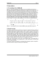
Figure 2.11 shows the backplane for the flashlink 40-channel DWDM optical filter frame. 
Each optical port supports a dedicated wavelength that is marked on the sub-rack frame. The 
connector is an SC/PC connector. Each port should be connected to the corresponding 
wavelength for each channel card with an optical patch cord. The common port supports all 
wavelengths in either direction and should therefore be connected to the single fiber between 
the two locations where the flashlink 40-channel DWDM system is installed. The optical 
filters are sold in pairs using cascaded thin film filters for wavelength selection. This means 
that the filters are mounted in opposite orders on the two sides. Those wavelengths which 
have lower attenuation in one end point have higher attenuation in the other end point, thus 
ensuring all channels have the same link loss. The specification of the optical filters can be 
found in chapter 2. One side is marked DWDM-40C-A, the other is marked DWDM-40C-B. 


Figure 3.1: The backplane for the 40-channel DWDM system optical filter (endpoint A)


3.2 System design 

The maximum insertion loss for any channel in end point A is 4.0dB, but the same channel in 
the complementary end point B will then have a maximum insertion loss of 1.5dB. Likewise 
the channel with maximum allowed insertion loss of 1.5dB in endpoint A will have a 
maximum insertion loss of 4.0dB in end point B. This means that there can theoretically be 
about 3dB difference in attenuation between two different channels (1.5dB variance across 
the band) after multiplexing. When using erbium doped fiber optical amplifiers (EDFA), this 
can lead to large differences in signal strength between different channels at the receiving 
end. The reason is that EDFAs also have a variance in gain across the wavelength band. 
Therefore a special uniform loss version (suffix -U) is available as an option. 

EDFAs used with DWDM-40C should have a gain flattening filter and operate close to 
nominal gain / input power. When operating over or under nominal gain, the EDFAs gain 
variance changes drastically. 

The minimum headroom that needs to be considered when designing a system increases for 
each EDFA because of the gain variance across wavelengths. 


network-electronics.com 

Содержание Flashlink DWDM-40C

Страница 1: ...network electronics com 40 ch 100GHz Dense Wavelength Division Multiplexing System Rev 0 Flashlink User Manual DWDM 40C...

Страница 2: ...9 Fax 47 33 48 99 98 Email support network electronics com www network electronics com Support Phone 47 90 60 99 99 Revision history Current revision of this document is the uppermost in the table bel...

Страница 3: ...Connections 7 3 1 Connecting to the DWDM 40C 7 3 2 System design 7 4 Operation 8 4 1 Handling of optical fibers 8 4 2 Laser safety precautions 8 4 3 Connector cleaning 9 4 4 Power dissipation in the...

Страница 4: ...ltiplexed signals The modules are bidirectional so they work as both multiplexer and demultiplexer at the same time A DWDM 40C consists of one DWDM 40C A and one DWDM 40C B which when used together pr...

Страница 5: ...ched pair including connectors 6dB max Channel Spacing 100GHz Passband ITU 12 5GHz Adjacent Channel Isolation 25dB min 28dB typ Non Adjacent Channel Isolation 40dB min Directivity 45dB min Thermal Wav...

Страница 6: ...9 48 194 80 1538 98 47 194 70 1539 77 46 194 60 1540 56 45 194 50 1541 35 Blue wavelengths 44 194 40 1542 14 43 194 30 1542 94 42 194 20 1543 73 41 194 10 1544 53 40 194 00 1545 32 39 193 90 1546 12 3...

Страница 7: ...ure 3 1 The backplane for the 40 channel DWDM system optical filter endpoint A 3 2 System design The maximum insertion loss for any channel in end point A is 4 0dB but the same channel in the compleme...

Страница 8: ...adius This means that any bending of the fiber corresponding to a bend radius less than the given value will make the light leak out of the fiber A typical value is 20 mm to 40 mm Telcordia standard f...

Страница 9: ...ied as Class 1 laser product according to EN 60 825 1 94 A11 96 and CFR Ch1 1997 Part 1040 10 If the front panel is removed the FR 2RU 10 2 is classified as Class 1 laser product according to EN 60 82...

Страница 10: ...aser wavelength will drift with changing temperature if the laser is not controlled This means that the internal temperature of the laser must be kept at a constant level for all operation temperature...

Страница 11: ...lower the internal package temperature The increased current will make more power dissipate thereby increasing the ambient temperature and so on To avoid this proper ventilation of the DWDM system is...

Страница 12: ...umidity range 90 non condensing 2 The equipment will operate without damage under the following environmental conditions Temperature range 5 C to 50 C Relative humidity range 95 non condensing 3 Elect...

Страница 13: ...d conditions for the product s covered by this manual follow the General Sales Conditions by Network Electronics ASA These conditions are available on the company web site of Network Electronics ASA w...

Отзывы: