DA-HDSDI
Rev. 4
DATE: 05 October 2007
Network Electronics ASA, P.O.Box 1020, N-3204 Sandefjord, Norway. Tel.: +47 33 48 99 99 – Fax: +47 33 48 99 98
4. Connector module
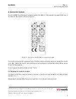
The DA-HDSDI has a dedicated connector module: DA-SDI-C1. This module is mounted at the rear of
the sub-rack. The module is shown in figure 6.
Figure 6 - Overview of the DA-SDI-C1 connector module
The electrical input signal is connected to the IN BNC and the electrical outputs are connected to the O1
to O6 BNC. Please note that O2, O4 and O6 has an inverted signal, so formats like DVB-ASI can not use
be used on these outputs.
Unused outputs should be terminated with 75 ohm.
4.1 Mounting the connector module.
The details of how the connector module is mounted, is found in the user manual for the sub-rack frame
FR-2RU-10-2.
This manual is also available from our web site: http://www.network-electronics.com/
E-mail: [email protected] – Web: http://www.network-electronics.com/
Technical specifications are subject to be changed without notice.
8


