2.
Package Checklist
1.
Overview
3.
Panel Layout
NA255A
The easy, cost-effective Netstor PCIe Gen3 to GPU desktop expansion
enclosure TurboBox NA255A features easy plug and play installation,
containing PCIe 3.0 ×16 host card, target card and data cable providing
high-speed data rate up to 128Gbps. Through the TurboBox NA255A,
all the PCIe slots on NA255A are available to the host PC, workstation,
or Mac Pro.
Before the installation of this unit, verify the package contains the
following items.
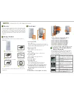
1. Power on/off button
2. Buzzer mute button
Green – normal
Red – over-temperature (higher than 55
℃
)
3. Fan LED
Green – normal
Red – fan failure (low frequency of RPM or stop)
4. Temperature LED
Green – normal
Red – over-temperature (higher than 55
℃
)
5. Power switch
6. Power receptacle
7. Link status LED
Gen3: constant green light
Gen2: fast blinking green light (2 flashes/second)
Gen1: slow blinking green light (1 flash/second)
8. Two external PCIe 3.0 ×8 connectors for host
connection (one port is etched with ×8 for
lane 1~8; the other port is etched with ×16
for lane 9~16)
9. PCIe slots
10. Thumbscrew to loosen/tighten the side door
Blue – power on
Note:
Under powering on/off NA255A by manual mode, to
power on/off the TurboBox NA255A, press the button for two
seconds until the button shows blue light or off.
1. Slot 1 : PCIe ×16 connector (×16 signal);
target card already installed in it.
2. Slot 2 : PCIe ×16 connector (×8 signal)
3. Slot 3 : PCIe ×16 connector (×8 signal)
4. Slot 4 : PCIe ×16 connector (×8 signal)
5. Slot 5: PCIe ×16 connector (×8 signal)
6. Slot 6: PCIe ×4 connector (×4 signal)
7. Slot 7: PCIe ×4 connector (×4 signal)
8. 8* 6+2 pin PCIe power cables for graphics cards
External PCIe 3.0 to GPU Desktop Enclosure
4.
Installation of PCIe Graphics/Add-On
Card and Connection
Before following the installation procedures, disconnect
TurboBox NA255A from power source to prevent electric
shock or damage to graphics/PCIe card. In order to
correctly configure NA255A to work properly with different
host PC or Workstation, the following jumper and switches
may need to be adjusted.
PCIe 3.0 ×16
host adapter card x 1
B
PCIe 3.0 ×8 cable
(1.5 meter) x 2
D
Power cord × 1
E
PCIe 3.0 ×16
target adapter card x 1 (Installed)
C
CD containing
user manual x 1
F
Green IT makes
Green Earth
NetStor Technology Co. Ltd.
www.netstor.com.tw
NA255A Enclosure x 1
A
If any of the above items is missing or damaged, please notify your sales
representative.
JP2
SW1-2
SW1
Function
Location
Function
Location
Function
Location
To set NA255A to Gen3 mode, place jumper
over pin 1 and pin 2. To set NA255A to Gen2
mode, NOT place jumper over pins. To set
NA255A to Gen1 mode, place jumper over
pin 2 and pin 3.
To set up connection between host and
NA255A for ×8 or ×16. For ×16 connection,
SW1-2 is ON. For ×8 connection, SW1-2 is
OFF.
To set up connection between host and NA255A
for ×8 or ×16. For ×16 connection, SW1 is OFF.
For ×8 connection, SW1 is ON.
Jumper JP2 is located near slot 3
on backplane
.
Switch SW1-2 is located near slot 5
on backplane
.
Switch module SW1 is located on top-right
position of host card
(NP970A-H)
and
target card
(NP970A-T)
.
1 2 3 4
10 5 6 7 8 9
1
6
2
3
4
5
7
5
4
3
2
1
6
8
7
Содержание TurboBox Xtreme
Страница 1: ......


