background image

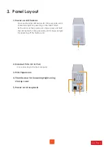
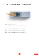
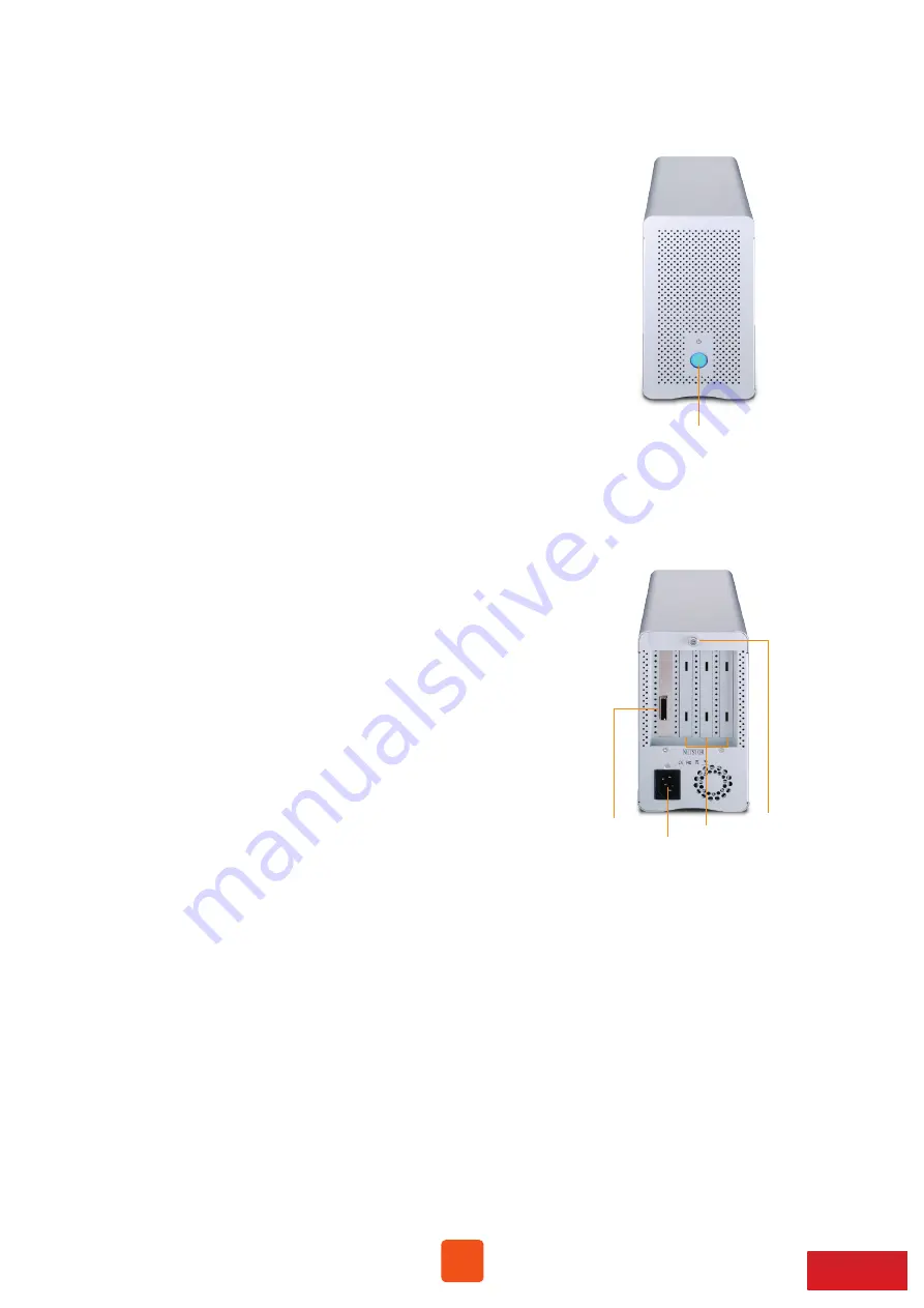
3.  Panel Layout

4

Go Top ↑

2. External PCIe 3.0 ×4 Port


For connecting to the host computer

3. PCIe Expansion

4. Thumbscrew for loosening/tightening 
    the top cover

5. Power cord receptacle

1. Power-on LED button

1

2

5

3

4

Press and hold the LED button for three seconds until it 

shows blue light for powering on the NA211A-G3.

As the unit is at the powered on status, press and hold 
the LED button for three seconds until it shows no light 

for powering off the Netstor unit.

Содержание NA211A-G3

Страница 1: ...First edition May 2019 User Manual NA211A G3 External PCIe 3 0 expansion chassis 3 slots with built in 300W power supply ...

Страница 2: ... NA211A G3 1 Overview 2 Package Checklist 3 Panel Layout 8 Fan Speed Adjustment 3 3 4 4 LED Status on Host card and Target card 5 6 7 7 Installation of Netstor PCIe 3 0 4 Host Card in Computer 10 11 9 Operation and Verification 12 14 9 2 macOS 12 9 1 Windows Operating System ...

Страница 3: ...fessionals requirements for any demanding configuration at work This user s manual will help you set up the Netstor NA211A G3 enclosure 2 Package Checklist Before installing the unit verify the package contains the following items D E External PCIe 3 0 4 data cable 1 5 meter 1 C PCIe 3 0 4 host card 1 B Power cord 1 Carry bag 1 Enclosure x 1 A 3 Notify your sales representative if any of the above ...

Страница 4: ... tightening the top cover 5 Power cord receptacle 1 Power on LED button 1 2 5 3 4 Press and hold the LED button for three seconds until it shows blue light for powering on the NA211A G3 As the unit is at the powered on status press and hold the LED button for three seconds until it shows no light for powering off the Netstor unit ...

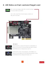
Страница 5: ...A211A G3 is NOT linked SW1 switch When SW1 switch is turned to the left position the NP963AG3 card will be set as the host card The LED1 will show red light to indicate the NP963AG3 card is configured as the host card As SW1 switch is turned to the right position the NP963AG3 card will be set as the target card The LED1 will show blue light to indicate the NP963AG3 card is configured as the target c...

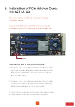
Страница 6: ... This is the upstream slot Note the target card cannot be moved Slot 2 PCIe x8 slot open type supports PCIe card x16 x8 x4 x1 Slot 3 PCIe x8 slot closed type supports PCIe card x8 x4 x1 Slot 4 PCIe x8 slot open type supports PCIe card x16 x8 x4 x1 slot 4 slot 3 slot 2 slot 1 ...

Страница 7: ...or the correct connection between host computer and NA211A G3 Two conditions A and B for connection are listed below A If computer s PCIe slot to be linked with NA211A G3 is PCIe 3 0 4 then you don t need to make any change to the switch setting on NA211A G3 slot board because NA211A G3 is already set to work with computer s PCIe 3 0 4 slot by default B If computer s PCIe slot to be linked with NA...

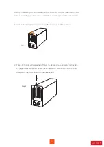
Страница 8: ...shock or damage to PCIe add on card 1 Loosen the thumbscrew and remove the top cover of the enclosure 8 Go Top Step 1 2 Three PCIe slots at rear panel of NA211A G3 are pre covered by removable L shape metal brackets Loosen the screw of the removable L shape metal bracket for the PCIe add on cards installation Step 2 ...

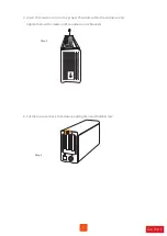
Страница 9: ...3 Insert PCIe add on cards in the proper PCIe slots within the enclosure and tighten them with screws on PCIe add on cards brackets 4 Put the top cover back to enclosure and tighten and thumbscrew Step 3 Step 4 ...

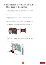
Страница 10: ...ng on the LED1 on host card will show red light to mean it s the correct configuration 4 Install Netstor PCIe 3 0 4 host card in the available PCIe 3 0 2 0 4 x8 x16 slot in computer Use the screwdriver to tighten the screw to host card s bracket in order to have the host card fastened to the computer chassis 5 Restore computer chassis cover 10 Go Top 7 Installation of Netstor PCIe 3 0 4 Host Card i...

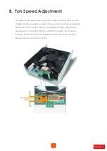
Страница 11: ...connector there are four sets of jumpers labeled 6V 8V 10V 12V from top to bottom The default setting is jumper being placed over pin 7 and pin 8 for 6V for medium fan speed The fan speed increases from 6V to 12V 12V full speed If all pins are open no jumper placed over pins the fan will not spin Pin No 6V 8V 10V 12V 2 1 4 3 6 5 8 7 ...

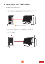
Страница 12: ...external PCIe 3 0 4 data cable 2 Firstly press and hold Netstor chassis front LED button for three seconds until it shows blue light for powering on the NA211A G3 and then power on the host computer 12 Go Top 9 Operation and Verification External PCIe 3 0 x4 data cable three seconds 9 1 Windows Operating System 2 1 ...

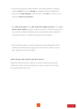
Страница 13: ... third party PCIe cards installed in NA211A G3 will be shown meaning that the PCIe cards within the Netstor chassis are recognized correctly by the host computer 5 After the Windows drivers for the third party PCIe cards within NA211A G3 are installed on the Windows operating system the PCIe cards in Netstor unit will work properly with the host computer Follow the procedure below to turn off the s...

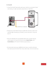
Страница 14: ...top left of the screen select About This Mac click System Report and the System Information pane will pop up 4 At System Information pane click PCI in the left column and all the third party PCIe cards installed in the NA211A G3 chassis will be shown in the information area 14 Go Top 1 Connect NA211A G3 chassis with power source and then connect Netstor chassis and tower Mac Pro with the included ...

Страница 15: ...R O C sales netstor com tw 886 2 2917 1500 6 After the Windows drivers for the third party PCIe cards within NA211A G3 are installed on the Windows operating system the PCIe cards in Netstor unit will work properly with the host computer 5 Verify the drivers for the third party PCIe cards in Netstor unit are installed on macOS As seeing all the PCIe cards are listed in PCI section at the last step...

Отзывы: