NETGEAR ReadyNAS 2100 Скачать руководство пользователя страница 29

ReadyNAS 3200, 4200 v1, 4200 v2

29

 NETGEAR ReadyNAS Rack-Mount Storage Systems
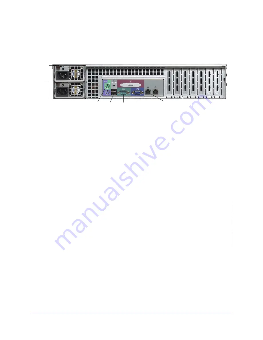
3200 Rear Panel

This following figure shows the rear panel of the 3200.

3

4

6

5

1

2

Figure 12. 3200 rear panel

1. Power supplies

2. PS2 keyboard and mouse ports

3. USB ports

4. RS232 console port

5. VGA monitor port

6. 1-gigabit Ethernet ports with LED status indicators

Содержание ReadyNAS 2100

Страница 1: ...350 East Plumeria Drive San Jose CA 95134 USA June 2011 202 10848 02 ReadyNAS Rack Mount Storage Systems Hardware Manual Models 1500 2100 3100 3200 4200 v1 4200 v2...

Страница 2: ...pport netgear com Website http www netgear com Phone 1 888 NETGEAR for US Canada only For other countries see your support information card Trademarks NETGEAR the NETGEAR logo and Connect with Innovat...

Страница 3: ...tallation 14 Technical Specifications 15 Chapter 3 ReadyNAS 3100 Front Panel 17 Rear Panel 18 Status Information 19 Boot Menu 20 Rack Mount Setup 22 Considerations 22 Installation 22 Technical Specifi...

Страница 4: ...ding a Disk 40 Replacing a Disk 43 System Components 45 X Change System Module 45 Individual Components 46 Appendix A Warnings and Precautions Safety Warnings 50 Electrical Safety Precautions 50 Gener...

Страница 5: ...owing sections System Shutdown Factory Settings For detailed information about configuring managing and using your ReadyNAS rack mount storage system see the ReadyNAS for Business Software Manual whic...

Страница 6: ...ing table lists factory settings for ReadyNAS rack mount storage systems Table 1 Factory settings Feature Default Login User login URL when the ReadyNAS is not connected to a DHCP server https 192 168...

Страница 7: ...500 and 2100 This chapter describes the physical features of the ReadyNAS1500 and 2100 It includes the following sections Front Panel Rear Panel Status Information Boot Menu Rack Mount Setup Technical...

Страница 8: ...NAS 1500 and 2100 1 2 3 3 Figure 1 Front panel 1 Drive bays 2 Control panel 3 Mounting bracket The following figure shows the control panel in more detail 2 1 3 4 6 7 9 8 5 Figure 2 Control panel 1 Ba...

Страница 9: ...es a pop out tray handle as shown in the following figure 3 1 2 Figure 3 Disk tray handle and release latch 1 Disk tray lock 2 Disk release latch 3 Disk tray handle WARNING No matter how many hard dri...

Страница 10: ...the rear panel of the of the ReadyNAS 1500 and 2100 4 5 7 6 2 3 1 8 Figure 4 Rear panel 1 X Change system module thumb screw 2 System exhaust fans 3 Power switch 4 Power cable socket 5 Disk exhaust f...

Страница 11: ...w Disk synchronization or disk failure Panic Power button was pressed and held Marching Volume expansion is in progress Disk activity LED The disk activity LED has these states On A disk is active Bli...

Страница 12: ...rashes and corrupts some configuration files OS reinstall boot mode also resets some settings on your unit such as Internet protocol settings and the administrator password to defaults Tech support Bo...

Страница 13: ...ED illuminate 5 Press and release the Backup button to scroll through the boot menu modes The following table lists the boot menu s LED status blink pattern which you can use to identify boot mode opt...

Страница 14: ...circuitry and the effect that any possible overloading of circuits might have on overcurrent protection and power supply wiring Consider equipment nameplate ratings when addressing this concern Relia...

Страница 15: ...aring chassis cooling fans Fan failure alerts Hardware LED software via FrontView and high temperature email alert with auto shutdown option Operating Environmental Temperature 0 to 40 C 32 to10 4 F H...

Страница 16: ...eadyNAS 3100 This chapter describes the physical features of the ReadyNAS 3100 It includes the following sections Front Panel Rear Panel Status Information Boot Menu Rack Mount Setup Technical Specifi...

Страница 17: ...front panel of the ReadyNAS 3100 3 1 2 Figure 5 Front panel 1 Drive bays with disk status LEDs 2 USB port 3 Control panel The following figure shows the control panel in more detail 4 5 3 2 6 1 Figure...

Страница 18: ...e 2 Disk tray release latch WARNING No matter how many hard drives are installed in your system ensure that all drive trays remain in the drive bays to maintain proper airflow Rear Panel This followin...

Страница 19: ...these states Green An Ethernet cable is connected Blinking An Ethernet cable is active Off An Ethernet cable is disconnected Ethernet port LEDs rear panel Two LED status indicators are built into thes...

Страница 20: ...es and corrupts some configuration files OS reinstall boot mode also resets some settings on your unit such as Internet protocol settings and the administrator password to defaults Tech support Boots...

Страница 21: ...button to scroll through the boot menu options The following table lists the fan LED blink pattern which you can use to identify boot mode options Boot Mode Fan LED Blink Pattern Normal Factory defau...

Страница 22: ...circuitry and the effect that any possible overloading of circuits might have on overcurrent protection and power supply wiring Consider equipment nameplate ratings when addressing this concern Relia...

Страница 23: ...ng kit 1 Extend the rail assembly by pulling it outward 2 Press the release tab and separate the inner rail from the outer assembly 3 Connect the rails 4 Use the provided mounting screws to mount the...

Страница 24: ...unt Storage Systems 5 Attach the chassis to the rack as follows a Extend the ball shuttle to the very front b Align the rails and push the chassis in c Secure the handles to the outer rails with screw...

Страница 25: ...re alerts Hardware LED software via FrontView and high temperature email alert with auto shutdown option Operating Environmental Temperature 0 40 C 32 10 4 F Humidity non condensing 20 80 Physical For...

Страница 26: ...v2 This chapter describes physical features of the ReadyNAS 3200 4200 v1 and 4200 v2 It includes the following topics Front Panel 3200 Rear Panel 4200 Rear Panel Status Information Boot Menu Rack Mou...

Страница 27: ...panel of the 3200 and 4200 1 2 Figure 9 Front panel 1 Drive bays with disk status LEDs 2 Control panel The following figure shows the control panel in more detail 1 2 3 4 5 6 7 8 Figure 10 Control pan...

Страница 28: ...at releases the pop out tray handle as shown in the following figure 2 1 Figure 11 Disk tray handle and release latch 1 Disk tray handle 2 Disk tray release latch WARNING No matter how many hard drive...

Страница 29: ...ystems 3200 Rear Panel This following figure shows the rear panel of the 3200 3 4 6 5 1 2 Figure 12 3200 rear panel 1 Power supplies 2 PS2 keyboard and mouse ports 3 USB ports 4 RS232 console port 5 V...

Страница 30: ...ng figure shows the rear panel of the 4200 3 4 6 5 1 2 7 Figure 13 4200 rear panel 1 Power supplies 2 PS2 keyboard and mouse ports 3 USB ports 4 RS232 console port 5 VGA monitor port 6 1 gigabit Ether...

Страница 31: ...sk tray The top LED indicates disk activity as follows Blinking The disk in the bay is active Off The disk in the bay is inactive The bottom LED indicates disk failure as follows Off Normal operation...

Страница 32: ...em crashes and corrupts some configuration files OS reinstall boot mode also resets some settings on your unit such as Internet protocol settings and the administrator password to defaults Tech suppor...

Страница 33: ...lease the Reset button to scroll through the boot menu options Watch the blink pattern of the power diagnostic LED and the fan LED The following table shows the how the system displays the current opt...

Страница 34: ...into a rack so that the amount of airflow required for safe operation is not compromised Mechanical loading Mount the equipment into a rack so that a hazardous condition does not arise due to uneven...

Страница 35: ...repare to work with it The rack mounting kit contains two rail assemblies Each assembly consists of two sections An inner fixed chassis rail that secures directly to the unit s chassis An outer fixed...

Страница 36: ...the outer rails to the rack with screws b Press the release to extend the rails c Hang the hooks of the rails into the rack holes and fasten the rails to the rack 4 Attach the chassis to the rack as...

Страница 37: ...ert with auto shutdown option Operating Environmental Temperature 0 40 C 32 10 4 F Humidity non condensing 20 80 Physical Form factor 2U rack mount with 12 hot swappable SATA drive bays Dimensions H x...

Страница 38: ...38 5 5 Maintenance This chapter describes how to perform maintenance activities like adding disks and replacing disks and system components It includes the following topics Disks System Components...

Страница 39: ...rform a factory default reboot as described in the boot menu section for your ReadyNAS unit 1500 and 2100 Boot Menu on page 12 3100 Boot Menu on page 20 3200 and 4200 Boot Menu on page 32 Note This pr...

Страница 40: ...number open the disk tray and take out the failed disk Use FrontView to determine the disk vendor and model used in your unit For information about setting up email alerts and using FrontView see the...

Страница 41: ...nd This could take several hours depending on the disk size You can continue to use your ReadyNAS although access is slower until the volume synchronization finishes You are notified by email when the...

Страница 42: ...of the disk bay when you reassemble the disk 4 Slide the disk tray into the unit and secure the handle The volume automatically synchronizes with the new disk in the background This could take severa...

Страница 43: ...orts hot swap bays so you do not need to power down your unit when replacing a disk To replace a disk on a 1500 or 2100 1 In the case of a failed disk scan the disk LEDs on the control panel to identi...

Страница 44: ...everal hours depending on the disk size You can continue to use your ReadyNAS although access is slower until the volume synchronization finishes You are notified by email when the process is complete...

Страница 45: ...although access is slower until the volume synchronization finishes You are notified by email when the process is complete System Components You can replace system components on your ReadyNAS rack mou...

Страница 46: ...r supply Replace a failed power supply with the same model To replace a power supply 1 Unplug the AC power cord from the failed power supply module 2 Depress the locking tab on the power supply module...

Страница 47: ...l illuminates and an email alert is sent to the system administrator Replace a failed fan as soon as possible Remove the top chassis cover while the system is still running to determine which fan fail...

Страница 48: ...hot plug feature causes the fan to start immediately upon being connected to its header on the mainboard Replacing the Onboard Battery Replace the battery with the same or an equivalent type recommend...

Страница 49: ...ns safety warnings and precautions for the ReadyNAS 1500 2100 3100 3200 and 4200 It includes the following sections Safety Warnings Electrical Safety Precautions General Safety Precautions Electrostat...

Страница 50: ...f switch disconnection switch or electrical outlet If an electrical accident occurs you can then quickly remove power from the system Do not work alone when working with high voltage components Always...

Страница 51: ...st be replaced only with the same or an equivalent type recommended by the manufacturer Dispose of used batteries according to the manufacturer s instructions DANGER There is a danger of explosion if...

Страница 52: ...cautions Ensure that the leveling jacks on the bottom of the rack are fully extended to the floor with the full weight of the rack resting on them In single rack installations stabilizers should be at...

Страница 53: ...States FCC Information to User This product does not contain any user serviceable components and is to be used with approved antennas only Any product changes or modifications will invalidate all appl...

Страница 54: ...the instructions may cause harmful interference to radio communications However there is no guarantee that interference will not occur in a particular installation If this equipment does cause harmfu...

Страница 55: ...g the following test methods and standards EN55022 2006 A1 2007 EN55024 1998 A1 2001 A2 2003 EN60950 1 2005 2nd Edition EN 61000 3 2 2006 EN 61000 3 3 1995 w A1 2001 A2 2005 GPL License Agreement GPL...

Страница 56: ...27 CX4 PCIe card 31 D disk failure 40 disk adding 40 disk failure 40 disk replacing 43 disks previously formatted 39 disks supported 39 drive bay 1500 9 2100 9 3100 18 3200 28 4200 28 E electrical saf...

Страница 57: ...22 3200 34 4200 34 rack mount precautions 52 rear panel 18 29 1500 10 2100 10 3100 18 3200 29 4200 30 S setup location 1500 14 2100 14 3100 22 3200 34 4200 34 SFP PCIe card 31 side panel 8 socket outl...

Отзывы: