background image

  Administrator’s Guide and Operating Instructions 


28 


„

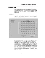
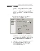
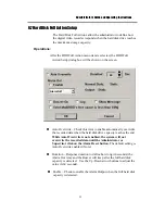
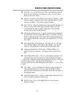
Tag Color – To select the text color of the corresponding camera tag 
name. Use the Up/Down arrow buttons to select, the color will be 
shown on the screen above.   

„

Installed – Check this item if the selected Camera is installed.    If the 
selected Camera is installed, all the items in the Behaviors For Each 
Camera are settable.    The default setting is installed. 

„

PTZ / PTZ ID – Check the PTZ item and enter the PTZ ID number if 
the selected camera is a PTZ camera. The ID number has to be 
consistent with the camera setting. Please refer to the operating 
manual of the camera for the IDsetting.   

„

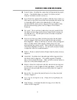
PTZ Setting(For all camera) – To define the Model Type, Baud Rate 
and Data Type of all the installed PTZ camera. Use the Down Arrow 
button to select the proper items. Please refer to the specification of 
the camera for the setting. The system now supports Pelco C1487M 
type camera. 

„

Recording Quality For All Cameras – The range is 0-10, with 0 the 
lowest (rough) quality, 10 the highest (fine) quality.    The default 
value is 8 . Use the Up/Down arrow buttons to adjust the value. 

„

Compression Method For All Cameras – MPEG (MPEG-1) or 
JPEG-CIF (JPEG), resolution – 352x240 for NTSC, 352x288 for 
PAL. 

„

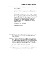
Enable Digital Watermark – Check to enable digital watermark. The 
system provides up to 64 positions to locate the digital watermark.     

                Click on the Vertical Position and Horizontal Position items to select the 

desired location. For the vertical position, the number 0 ~ 7          is 
from up to down, for the horizontal position, the number 0 ~ 7 is from left 
to right.   

„

Time Stamp – Click on the button for the Time Stamp setting menu.   
The system provides user options to enable/disable Time Stamp 
function, select the font size, position and color of the time stamp on 
the playback image.   

„

Enable Motion Detection – Check to enable motion detection for the 
selected Camera at the selected Time Type. 

„

Motion Action – The corresponding Motion Action if motion 
detection enabled. 

Содержание PowerPlex EDR400

Страница 1: ...INSTRUCTION MANUAL EDR400 4 CHANNEL DIGITAL VIDEO RECORDER Before installing and using this unit please read this manual carefully Be sure to keep the manual handy for later reference ...

Страница 2: ...diate radio frequency energy and if not installed and used in accordance with the instruction manual may cause interference to radio communications Operation of this equipment in a residential area is likely to cause harmful interference in which case the users will be required to correct the interference at their own expense Changes or modifications not expressly approved by the party responsible...

Страница 3: ...o not expose the appliance to water or moisture nor try to operate it in wet areas Do take immediate action if the appliance becomes wet Turn the power off and refer servicing to qualified service personnel Moisture may damage the appliance and also cause electric shock Do not use strong or abrasive detergents when cleaning the appliance body Use a dry cloth to clean the appliance when it is dirty...

Страница 4: ...tup 6 5 Motion Action Setup 6 6 Video Loss Action Setup 6 7 Hard Disks Full Action Setup 6 8 Camera Setup 6 9 Alarm In Setup 6 10 Alarm Out Setup 6 11 Display Sequence Setup 6 12 Display Page Setup 6 13 Motion Setup 6 14 Password Setup 6 15 System Configurations 6 16 Audio Setup 7 PTZ Control Functions 8 Day Time Setup Administrator 9 Image Playback and Archive Administrator Supervisor 9 1 Select ...

Страница 5: ...g or both Up to 5 seconds of pre record time Built in MPEG 1 and JPEG compression decompression with configurable quality Storage on 3 5 Docking Hard Disk hot swappable DVR option Versatile display formats full screen 4 7 9 10 13 16 video Alarm history log for Video Loss Motion Alarm input Hard Disk Full and Power Multi level password to ensure high degree of security Configurable Recording Event ...

Страница 6: ...decoder decodes the digitized format no matter it is JPEG or MPEG 1 and then displays the decoded pictures on the VGA monitor screen 1 2 3 Video Storage and Retrieval The encoded pictures are stored in the hard disks with the stored frame rate for each camera set by the administrator If any event Alarm Motion or Video Loss happens all the encoded pictures for the correspondent camera for the prese...

Страница 7: ... previously recorded hard disk to review the recorded video Displaying of the recorded video is composed of decoding the JPEG or MPEG 1 encoded video automatically and multiplexing each camera video to its designated video window With the coded data that was inserted into each recorded picture the digital video recorder can reconstruct each camera s tag name status date and time information automa...

Страница 8: ...0V DC power source 2 Camera 1 Video Input BNC connector for Camera 1 3 Camera 2 Video Input BNC connector for Camera 2 4 Camera 3 Video Input BNC connector for Camera 3 5 Camera 4 Video Input BNC connector for Camera 4 6 75ohm Termination Normally the termination should be set as On However if the corresponding camera is connected to other devices please set it as Off 7 VGA Monitor Output 8 RS 232...

Страница 9: ...2 Mouse Y Cable Connector Connects to the PS2 mouse or the Y cable attached for the mouse and keyboard optional connection The mouse must be connected at system startup 13 Audio In 14 Audio Out 15 2 USB connectors Connect to the CD RW DVD RAM ZIP printer or USB hub 16 LAN connector 1 For peer to peer connection reserved 17 LAN connector 2 Connects to the RJ45 LAN connector 18 Reset Button 19 LEDs ...

Страница 10: ...de Panel 20 Hard Disk Tray Please make sure to set the hard disk as master To access the hard disk use the attached key to open the cover and remove the hard disk holder The key can t be removed from the cover while the cover is open 21 Cooling FAN 20 21 ...

Страница 11: ...ating Instructions 7 3 System Installation The installations described below should be made by qualified service personnel or system installers 3 1 Before Installation Please refer to the following diagram for the system connections ...

Страница 12: ...use connector Hard Disk Make sure the hard disk is inside the hard disk tray Power Connect the DC 24V power source or the AC adapter into the power socket 3 3 Optional Connections Alarm In Connect Alarm In 1 4 to NC or NO type of alarm signals Please make sure to setup the software configurations of Alarm In accordingly Alarm Out Connect Alarm Out 1 2 to NC type of alarm signals Alarm Out 3 4 to N...

Страница 13: ... other audio devices to the Audio In Audio out connector PTZ Camera Connect the PTZ camera to the RS 232 2 connector The system can supports Pelco C1487M type camera Ethernet eDR400 is enabled control from the PC via Ethernet Connect the LAN connector to a standard RJ45 connector Ethernet cable Shown in below is an example of connection Modem eDR400 is enabled control from the PC via modem Connect...

Страница 14: ...essible in the current mode or login right The followings are a brief description for each of the icons System time in military hour format Move the cursor on it and the system date will be shown in YYYY MM DD format Shutdown To shutdown the system Note Playback Controls To change the control icons to those for playback functions Alarm Reset To reset the Alarm Outputs to their normal states and si...

Страница 15: ...c Page Mode 7 window Display Static Page Mode 9 window Display Static Page Mode 10 window Display Static Page Mode 13 window Display Static Page Mode 16 window Display Static Page Mode Pause Circulate To toggle between Pause Mode and Circulate Mode for status indication Next Device To change the status indication to next device while it s in Pause Mode Hard Disk Storage Indicator To indicate the s...

Страница 16: ...re are 5 different colors GRAY BLACK Not existent or not installed GREEN Normal YELLOW Video Loss detected for Camera Alarm for Alarm Input Output and Recording for Hard Disk RED Motion detected for Camera Note To power down the system turn off the power source or unplug the power cord after the system is completed shutdown and the power down message is shown on the screen 4 1 View Display Print I...

Страница 17: ... will be shown on the screen The following is a brief description for each item shown above Camera Use the down arrow button to select the camera to display on this view window Live Playback To select to show live or playback image on this view window Please refer to Chapter 8 for the details of Image Playback and Archive Print To print the image shown this view window Switch To Full Screen Check ...

Страница 18: ...fault value for both of them is o for Supervisor the factory default value for both of them is s The system allows up to 5 user accounts for each login level The administrator can set up login name and password for each individual user please refer to Chapter 6 14 for detail setting The Operator can operate all the icons related to live video display the Supervisor can operate all the icons relate...

Страница 19: ...l button to delete all the event logs For the alarm and motion action if the action happened during the post record time from the previous triggered action there will be no event record 5 1 Version Display Click on the logo icon on the upper right corner the software version of the system and a serial number will be shown on the screen 5 2 Alarm Message Display The alarm message will be displayed ...

Страница 20: ...s of the system please click on the Config icon The configuration menu will pop up as below Click on the menu item for the respective configuration For the details of each item please refer to the following paragraphs Click on the Exit menu item to exit the setup You may be asked to restart the system for those new settings to take effect Note If the system is in Sequence Mode display please refer...

Страница 21: ...ver you may configure up to 16 Time Types to suit your needs Use the meaningful names no matter they are from human viewpoint or the system s viewpoint Some other meaningful names may be Day Night Overtime Code 1 Normal Alert etc Operations After the Time Type menu item is selected the Time Type dialog box will be shown on the screen Please click on the item in the Time Type List then click on the...

Страница 22: ...e menu item is selected the Day Type Setup dialog box will be shown on the screen Please click on the item in the Day Type List then click on the Day Type Tag and then enter the new tag name for the selected Day Type by using the mouse or the keyboard The Detail box corresponds to the selected Day Type shown in the Day Type Tag Please click on the Up Dn buttons to scroll the 16 time segments click...

Страница 23: ...The active month is shown on the upper corner of the screen The selectable Day Types are shown on the left corner of the screen Please click on the Day Type button to select the active Day Type the button will be on the DOWN position Click on the Calendar Day button to change its Day Type to the active Day Type or click on the weekday button to change the corresponding weekdays to the active Day T...

Страница 24: ...e Alarm Action menu item is selected the Alarm Action Setup dialog box will be shown on the screen Please click on the item in the Action List then click on the Action Tag and then enter the new tag name for the selected Action by using the mouse or the keyboard All the other settings correspond to the selected Action shown in the Action Tag The following is a brief description for each item shown...

Страница 25: ...all be recorded at Alarm Recording Rate However the Post record time will be prolonged if there is another Alarm Action triggered during the post record duration from the previous action Please refer to Camera Setup for Alarm Recording Rate of Camera Use the Up Down arrow buttons to adjust the value 0 seconds 60minutes Enable Check to enable the Alarm Output when the Alarm Action is triggered Alar...

Страница 26: ... Please refer to Chapter 6 15 for e mail notification setting Network Alarm Reserved function SMS Reserved function Note 1 When the Alarm Input that triggered the Alarm Action returns to normal the internal buzzer and the corresponding Alarm Output will return to normal immediately Note 2 The processing power for the system is 25 FPS for PAL and 30 FPS for NTSC So if the total configured recording...

Страница 27: ...ected the Motion Action Setup dialog box will be shown on the screen Please click on the item in the Action List then click on the Action Tag and then enter the new tag name for the selected Action by using the mouse or the keyboard All the other settings correspond to the selected Action shown in the Action Tag Please refer to the Alarm Action Setup for the descriptions and operations except the ...

Страница 28: ...m is selected the Video Loss Action Setup dialog box will be shown on the screen Please click on the item in the Action List then click on the Action Tag and then enter the new tag name for the selected Action by using the mouse or the keyboard All the other settings correspond to the selected Action shown in the Action Tag Please refer to the Alarm Action Setup for the descriptions and operations...

Страница 29: ...ble automatically overwrite the recorded data when the hard disk drive capacity reaches the end While Auto Overwrite is not enabled the system will not overwrite the recorded data until the Administrator or Supervisor click on the Alarm Reset button The default setting is Auto Overwrite enabled Note Duration Response duration to define how long in seconds the Alarm Out relay and the Buzzer will ke...

Страница 30: ... internal buzzer or not when the full hard disk capacity is detected Log Log to event log list or not Please refer to Log Display for the details Show Message To display the alarm message or not when the full hard disk is detected Send Mail Check to activate the e mail notification function There will be an e mail notification sent to the defined receivers while the hard disk capacity is less than...

Страница 31: ...will be shown on the screen Please click on the item in the Camera List then click on the Camera Tag and then enter the new tag name for the selected Camera by using the mouse or the keyboard The Recording Quality and the Compression Method apply to all cameras For the Behaviors For Each Camera please click on the item in the Time Type list to select the Time Type All the other settings correspond...

Страница 32: ...upports Pelco C1487M type camera Recording Quality For All Cameras The range is 0 10 with 0 the lowest rough quality 10 the highest fine quality The default value is 8 Use the Up Down arrow buttons to adjust the value Compression Method For All Cameras MPEG MPEG 1 or JPEG CIF JPEG resolution 352x240 for NTSC 352x288 for PAL Enable Digital Watermark Check to enable digital watermark The system prov...

Страница 33: ... selected Camera at the selected Time Type Use the Up Down arrow buttons to adjust the value 0 30 The default value is 5 Frame Per Second or 300 Frame Per Minute Note 1 The maximum recording rate for the system is 25 FPS for PAL 30 FPS for NTSC If the total recording rate for all cameras is greater than 25 30 FPS the system will decrease the recording rate for each camera averagely to make the tot...

Страница 34: ... click on the Alarm Input Tag and then enter the new tag name for the selected Alarm Input by using the mouse or the keyboard For the Alarm Action for each Alarm Input please click on the item in the Time Type list to select the Time Type All the other settings correspond to the selected Alarm Input shown in the Alarm Input Tag and the highlighted Time Type in the Time Type list The following is a...

Страница 35: ...se the Down arrow button to select the signal type Enable Alarm Action Check to Enable Alarm Action for the selected Alarm Input at the selected Time Type Alarm Action The corresponding Alarm Action if the Alarm Input changes its state from normal to alarm Up to 4 Alarm Actions are selectable 6 10 Alarm Out Setup ...

Страница 36: ... AO 3 4 for the system Operations After the Alarm Out menu item is selected the Alarm Out Setup dialog box will be shown on the screen Please click on the item in the Alarm Out List then click on the Alarm Out Tag and then enter the new tag name for the selected Alarm Output by using the mouse or the keyboard Define the behavior of the selected Alarm Output in the Trigger item click on On to enabl...

Страница 37: ...ll be shown on the screen The following is a brief description for each item shown above Number of Sequences Up to 2 sequences can be defined Use the Down arrow button to select the number Sequence Number To select the Sequence you want to modify for the following 2 items Number of Pages Number of Pages for the Sequence shown in Sequence Number Different Display Types have different maximum number...

Страница 38: ...wn on the screen Please select Sequence Mode or Static Page Mode first For Sequence Mode you may select the Sequence No then set the Page No and Dwell Time for Static Page Mode you may set the Display Type The following is a brief description for each item shown above Sequence Mode To set the Display Pages for Sequence Mode display Static Page Mode To set the Display Pages for Static Page Mode dis...

Страница 39: ...row button to select the number Page Dwell Time The Dwell Time in seconds for the selected Page shown in Page No Use the Down arrow button to select the number The default value is 5 Display Type To select the Display Type in Static Page Mode display Use the Down arrow button to select the Display Type The available types are 1 window Full screen and 4 window ...

Страница 40: ...be shown on the screen Please select the Camera and the Time Type first All the other settings correspond to the selected Camera and the selected Time Type shown in their respective fields For the Detection Area please click on the Set Clear button then click in the video window and drag the mouse to set clear the detection area To set the Sensitivity please click on the slider and drag the mouse ...

Страница 41: ...ue and Its Slider Showing the sensitivity for the selected Camera and Time Type Dragging the mouse on the slider to change the value The default value is 50 Trend Curve Window Trend curve showing the continuous snapshots of the detected motion with the bar higher than the horizontal line in the middle as motion detected lower as no motion detected Reset All button To reset all the settings to thei...

Страница 42: ...m is selected the Password Setup dialog box will be shown on the screen Please click on the item in the User Account list the information shown in Detail corresponds to the selected item To modify the user information simply click on each item and enter the desired login name and password enter the password again in the confirm field then click on Modify button to confirm the changes To setup a ne...

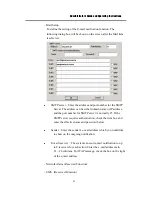
Страница 43: ...e shown on the screen The following is the brief description for each item shown above ŶҏCommunication LAN Card Configuration IP address Enter the desired IP address of the device in the columns To obtain the IP address please contact your Internet Server Provider Subnet Mask Enter the corresponding Subnet Mask Enable Gateway For local network setting leave the box blank to disable gateway For Int...

Страница 44: ...lout detail Reserved Function 192 168 0 1 192 168 0 2 admin admin Administrator s Guide and Operating Instructions 40 Gateway IP address Enter the corresponding IP address while the gateway is enabled Domain Name Server IP Address Enter the correct Domain Name Server for mapping Domain Names to IP addresses The default setting is 168 095 001 001 The user can also defines their local Domain Name Se...

Страница 45: ...dress and the port number for SMTP server is normally 25 If the SMTP server requires authentication check the item box and enter the effective name and password below Sender Enter the sender s e mail address which you would like to show on the outgoing notification E mail receiver The system can send e mail notification to up to 8 receivers for each action Enter the e mail addresses in 1 8 columns...

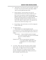
Страница 46: ... all the configuration setting to default value ҏ Ŷ Daylight Saving Time Check the Enable box to enable Daylight Saving Time The system provides 2 versions of Daylight Saving Time as described in below select the proper one while the Daylight Saving Time function is enabled North America Clocks are turned forward an hour begins at 2 a m on the first Sunday in April time reverts to standard time at...

Страница 47: ...ected to the system Operations After the Audio item is selected the Audio Setup dialog box will be shown on the screen Please check the box on Audio Installed item if it is installed to the system Click on the item in the action list the Normal Record option is corresponding to the selected item Click on ON to enable Normal Record at this selected time type Click on OFF to disable Normal Record ...

Страница 48: ...ny item is grayed it means the specific function is currently not accessible or the PTZ camera does not support the function Ŷ Preset To define the preset position adjust the camera to the desired position select the preset number 1 10 by the down arrow button then click Set button to confirm the setting To direct the camera to the preset position select the desired preset number by the down arrow...

Страница 49: ... Click on Auto Pan button again to stop running Ŷ Sequence To enable Sequence Mode In sequence Mode the camera will go to each preset position sequentially by the preset dwelling time Select the dwelling time 3 60sec from the above column by using the down arrow button then click on Seq button to start the Sequence Mode Click on Seq button again to stop Ŷ Iris To adjust the brightness level of the...

Страница 50: ...nistrator If you are an Administrator please click on the Time displaying on the Main Screen to enter the Date Time Setup for the system The date is in YYYY MM DD format whilst the time in military hour format HH MM SS The built in real time clock will be updated accordingly ...

Страница 51: ...ame as in the Main Screen provide the same functions as described in Chapter 4 If any icon is grayed it means that the specific function is not accessible in the current mode If you want to playback the recorded video please click on the Select HDD Range icon first to select the range of the recorded video for playback The following is a brief description for each of the icons not described in Cha...

Страница 52: ... video Click on Play icon to resume playing Archive Video Toggle button to enable disable retrieving playback video to CD RW DVD RAM ZIP disk etc When the video is playing back and Archive is enabled button at DOWN position the Retrieval Device and Camera dialog box will be shown please follow the instructions to retrieve the video Note 1 2 Replay To repeat playing the selected video over and over...

Страница 53: ... software Nero Burning and In CD come with CD RW or DVD RAM in the package please install them in a normal PC then you may format the medium by In CD To format the medium insert the medium to the CD RW or DVD RAM and run the In CD software follow the step as directed to complete the formatting As not all the CD RW DVD RAM is compatible with the system please contact your local distributor for the ...

Страница 54: ...is a brief description for each item shown above HDD No The recorded Hard Disk to playback Start End Block No 1 GB Block or 32 Sections Block for the system The maximum End Block No represents the Block number for the last recorded video or the maximum block number for the Hard Disk Use the Down arrow button to select the Start End Block No Options to Play To playback all recorded video images or ...

Страница 55: ...HH MM SS format for the video corresponding to the Slider Bar position If Block Section Slice is shown as nn XX XX the messages are at the Block level nn nn XX Section level and nn nn nn Slice level Ŷ Set Start button Drag the Slider Bar to the start position you want then click on the Set Start button to change the Start Block Section Slice No Ŷ Set End button Drag the Slider Bar to the end posit...

Страница 56: ...re the same as the above description To search by event the diagram will be shown as below Select the desired event from the event list The other items are the same as the above description 10 Remote Control V 01 01 01 2002 6 05 Wed 14 45 05 N Y N N N Y Y N N N Y Y N N N N N Y N N N Y Y N N N Y Y N N N N N Y N N N Y Y N N N Y Y N N N N N Y N N N Y Y N 02 06 05 14 45 05 14 55 05 02 06 05 N Y N N N ...

Страница 57: ... connection The user can either dial directly into the server through modem or connect over a network You must obtain IP addresses for the remote PC and eDR400 please refer to Chapter 6 15 System Configurations for the details Remote View After the Remote PC and eDR400 are connected start your Web browser and enter the system IP address in the Location Address field Note 1 Example The main page wi...

Страница 58: ... or Image Playback for each window Click on the Submit button while the setting is completed PTZ Click on the PTZ button a PTZ control panel will be shown on the screen Select the camera number the other control functions are the same as on eDR400 Please refer to Chapter 7 for PTZ Control Functions Click on PTZ button again to hide the PTZ control panel Playback Date Time To set the searching date...

Страница 59: ... or above 1024 x 768 If the PC is protected by the Firewall please make sure Port 1600 is enabled before accessed Note 2 The Login Name and Password are the same as used in eDR400 the Administrator can operate all the functions on remote end the Supervisor can view the live video and playback image and the Operator can only view the live video Note 3 You must have the upgrading software in your re...

Страница 60: ...ty Video Loss Detection Yes Event Log Yes User Interface Windows look and feel Setup On screen setup User Input Device Mouse Keyboard optional Buzzer Yes Timer Built in real time clock Watch Dog Timer Yes Title 10 character title generator for each camera alarm input and alarm output CompactFlash Memory 64 MB Security Multi level password protection System Recovery Auto power on after power loss r...

Страница 61: ...1 33 17 5 78 7 10 151 16 53 0 6 56 4 28 130 11 56 252 20 8 0 3 112 8 57 260 23 53 505 16 17 0 2 168 13 25 391 11 50 758 12 26 0 12 280 22 23 652 11 44 1264 4 44 0 1 337 2 51 782 23 41 1517 0 53 NTSC MPEG 1 Total Capture Rate Fine 10 Normal 5 Rough 0 FPS day hour min day hour min day hour min 30 1 12 24 3 23 29 6 1 38 15 3 0 49 7 22 59 12 3 16 10 4 13 13 11 22 29 18 4 54 6 7 14 2 19 21 29 30 8 10 3...

Страница 62: ...1 2 262 9 45 511 0 2 0 17 165 9 10 385 21 24 751 11 21 0 1 281 3 35 656 0 23 1277 12 7 PAL MPEG 1 Total Capture Rate Fine 10 Normal 5 Rough 0 FPS day hour min day hour min day hour min 25 1 12 35 4 1 5 6 1 38 12 5 3 1 11 8 2 10 12 3 16 8 3 4 14 14 12 4 26 18 6 39 5 7 14 59 20 5 27 30 8 10 2 5 15 5 59 40 10 54 60 16 21 1 7 22 10 13 59 11 47 89 5 41 1 38 2 59 101 3 15 151 16 53 0 83 45 22 23 121 20 ...

Страница 63: ... better video quality A The quality of JPEG is better than MPEG and the higher the recording quality the better the quality Please login as administrator click on the Config icon and then click on the Camera Setup menu item Select the Recording Quality and the Compression Method as appropriate After exiting the Config menu you ll be asked to restart the system for the new settings to take effect Q...

Страница 64: ...ad QuickTime from www apple com to play the MOV files The playback version of QuickTime is free Q Why does the system have the confused images in some channel A We suggest you to check if there s any camera with Line Lock function on The camera frequency is according to AC power if line lock function is set as ON the instable frequency of power supply will cause the variant frequency to camera Whe...

Страница 65: ... 61 2 9674 2520 ness ness com au NSW 4 167 Prospect Highway Seven Hills NSW 2147 Ph 02 8825 9222 Fax 02 9674 2520 sales ness com au VIC 24 Terracotta Drive Blackburn VIC 3130 Ph 03 9875 6400 Fax 03 9875 6422 nessmelb ness com au QLD Unit 3 471 Lytton Road Morningside QLD 4170 Ph 07 3399 4910 Fax 07 3217 9711 nessbris ness com au WA Unit 1 567 Newcastle Street Perth WA 6000 Ph 08 9328 2511 Fax 08 9...

Отзывы: