SKG4-E Gas Fired Humidifier
Installation Instructions and User Manual
Page | - 59 -
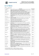
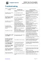
List of Alarms
Table 17 - List of Alarms
Display
Description
Alarm Reset
AirFlow
Indicates that the airflow sensor is open. Verify that the signal from the airflow sensor is
present at the controller’s input on the PCB and verify wiring.
Automatic
SupplyHighLimit
Indicates that the high limit item is open. Verify that the signal from the supply high limit
sensor is present at the controller’s input on the PCB and verify wiring.
Automatic
Interlock
Indicates that the interlock and the cut-out circuitry are open. Verify that the signal from
the interlock sensor is present at the controller’s input on the PCB and verify wiring.
Automatic
HighLimitCutout
Indicates that the high limit cutout has been activated due to a humidity reading that
exceeds the high limit setpoint. Ensure that the high limit humidistat is operating
correctly and that the distance between the sensor and the steam dispersion manifold
is sufficient (4.6 m).
Automatic
WtrLvl1 to 4
Indicates that the water level sensor is defective or incorrectly wired. Check sensor and
verify wiring.
Automatic
ChimneyTemp1 to 4
Indicates that the flue gas temperature sensor is defective or incorrectly wired. Check
sensor and verify wiring.
Automatic
WtrTemp1 to 4
Indicates that the evaporation chamber water temperature sensor is defective or
incorrectly wired. Check sensor and verify wiring.
Automatic
AmbientTemp1 to 4
Indicates that the weather proof enclosure temperature sensor is defective or
incorrectly wired. Check sensor and verify wiring.
(Only applicable for humidifiers with the weather proof enclosure.)
Automatic
FoamSensor1 to 4
Indicates that the foam cutout sensor is defective or incorrectly wired. Check sensor
and verify wiring.
Automatic
FailedPump
Indicates that there was an error during draining due to a pump failure. Verify that the
drain pump is operating correctly and that it is not being hindered or obstructed.
Manual *
FillTimeout
Indicates that the water level sensor has not reached the desired value within the
programmed delay. Verify and remove any obstructions in the water inlet line and verify
that the shut-off valve is not closed.
Manual *
BlockedPiping
Indicates that there was an error during draining due to a blockage in the pipes. Verify
and remove any obstructions in the piping and ensure that the drain outlet is not
clogged.
Manual *
HeatTimeout
Indicates that the water temperature in the evaporation chamber has not reached the
boiling point within the programmed delay. Verify the temperature of the supply water.
Manual *
Overheat
Indicates that the evaporation chamber temperature sensor has detected a
temperature reading greater than or equal to 105°C. Verify the operation of the water
level sensor and ensure that the water supply piping is not obstructed.
Manual *
WaterLeak
Indicates that a water leak has been detected. Verify the water line for signs of leaks
and ensure that all piping and water connections have been properly installed and
secured.
Manual *
Foaming
Indicates that there have been three foaming events detected in the last hour. Verify
the quality of the supply water. If chemical products were used to clean the evaporation
chamber during maintenance, rinse the chamber properly with water before re-installing
the chamber.
Manual *
BurnerLocked
Indicates that the burner did not ignite after three consecutive attempts. Verify that the
igniter and the ignition controller are working properly.
Manual *
FanDefect
Indicates that there is no feedback from the burner fan after receiving a control signal
from the controller. Verify that the status and connections of the burner fan and replace
if defective.
Manual *
FailedComm
Indicates that there was a communication error between modules. Verify that the
communication cable between the master and slave PCB boards is properly connected
and is not defective.
Manual *
ChimTempHi
Indicates that the flue gas temperature sensor has detected an elevated flue gas
temperature reading. Verify the operation of the water level sensor and flue gas
temperature sensor.
Manual *
FanBlocked
Indicates that there is a problem with the burner fan. Verify the operation of the fan and
ensure that there are no obstructions in the way.
Manual *
SystBlck
Indicates that one of the humidifier modules is responsible for a global alarm causing
the entire system to be unable to function. Verify the operation of the affected module
to determine the source of the problem.
Manual *
ServiceDue
Indicates that the due date for servicing the humidifier has arrived. See Service section
on page 62 for details.
Manual **
* Use
Reset Alarms
function in
Request
setting (see page 54).
** Use
Reset Counters
function in
Request
setting (see page 54).
Содержание SKG4-E Series
Страница 70: ...Notes ...
Страница 71: ......

