NEP BDM-300-208A Скачать руководство пользователя страница 9


7. TROUBLESHOOTING AND MAINTENANCE 

WARNING: 

DO NOT ATTEMPT TO REPAIR THE BDM-300; IT CONTAINS NO USER-

SERVICEABLE PARTS. IF TROUBLESHOOTING METHODS FAIL, PLEASE RETURN THE BDM-300 TO 

YOUR DISTRIBUTOR FOR MAINTENANCE.   

WARNING: 

NEVER DISCONNECT THE DC WIRE CONNECTORS UNDER LOAD. ENSURE THAT 

NO CURRENT IS FLOWING IN THE DC WIRES PRIOR TO DISCONNECTING. AN OPAQUE 

COVERING MAY BE USED TO COVER THE MODULE PRIOR TO DISCONNECTING   

WARNING: 

ALWAYS DISCONNECT AC POWER BEFORE DISCONNECTING PV MODULE WIRES 

FROM BDM-300. THE AC CONNECTOR OF THE FIRST BDM-300 IN A BRANCH CIRCUIT IS 

SUITABLE AS A DISCONNECTING MEANS ONCE THE AC BRANCH CIRCUIT BREAKER IN THE LOAD 

CENTER HAS BEEN OPENED. 


WARNING: 

BDM-300 IS POWERED BY DC POWER FROM PV MODULES. MAKE SURE YOU 

DISCONNECT THE DC CONNECTIONS AND RECONNECT DC POWER TO WATCH FOR THE TWO 

SECONDS LED ON AND TWO SECONDS LED OFF AFTER DC IS APPLIED.   

LED indica

�o

o

f err

o

r   


err

o

r m

o

de (except f

o

r gr

o

unding err

o

r)   

The LED light 

ashes in 

red

 color. 


NOT

 c

o

mmunica

ng with BDG-256, and with n

o

 err

o

r   

The LED light 

ashes in 

orange

 color.   


gr

o

unding fault   

The LED light is in 

solid red

 color.   

Tr

o

ublesh

oo�

ng an in

o

perable BDM-250   

To troubleshoot an inoperable BDM-300, follow the steps in the order shown:   
1. Check the connec

on to the u

lity grid. Verify that the u

lity voltage and 

frequency are within allowable ranges shown in the label of BDM-300.   

2. Verify u

lity power is present at the inverter in ques

on by removing AC, then DC 

power. Never disconnect the DC wires while the BDM-300 is producing power. Re-

connect the DC module connectors, and then watch for the LED blinks.   

3. Check the AC branch circuit interconnec

on harness between all the BDM-300. 

Verify that each inverter is energized by the u

lity grid as described in the 

previous step.   

4. Make sure that any AC disconnects are func

oning properly and are closed. 

5. Verify the PV module DC voltage is within the allowable range shown in the label 

of BDM-300.   

6. Check the DC connec

ons between the BDM-300 and the PV module. 

7. PLC signal quality may be checked through the interface on the BDG-256 gateway.   

If the PLC signal is weak, it might be due to the distance between the micro 

Disc

o

nnec

ng a BDM-300 fr

o

m the PV M

o

dule   

To ensure the BDM-300 is not disconnected from the PV modules under load, adhere 

to the following disconnec

on steps in the order shown:   

1. Disconnect the AC by opening the branch circuit breaker. 


2. Disconnect the 

rst AC connector in the branch circuit.   

3. Cover the module with an opaque cover.   
4. Using a DC current probe, verify there is no current 

owing in the DC wires between 

the PV module and the BDM-300.   

5. Care should be taken when measuring DC currents, most clamp-on meters must be 

zeroed 

rst and tend to dri

 with 

me.   

6. Disconnect the PV module DC wire connectors from the BDM-300.   
7. Remove the BDM-300 from the PV array racking.   

Installing a replacement BDM-300   

1. A

ach the replacement BDM-300 to the PV module racking using hardware 

recommended by your module racking vendor 

 
2. Connect the AC cable of the replacement BDM-300 and the neighboring BDM-300 

to complete the branch circuit connec

ons.   

3. Complete the connec

on map and connect the PV Modules.   

1) Complete the connec

on map   

2) Each BDM-300 has a removable serial number located on the moun

ng plate. 

Enter this serial number into a BDG-256, and correspond it to a number in the 

connec

on map.   

3) Connect the PV Modules   

4) Completely install all BDM-300 and all system inter-wiring connec

ons prior to 

installing the PV modules.   

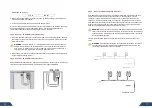
a) Mount the PV modules above their corresponding BDM-300. Each BDM-

300 comes with two oppositely sexed DC connectors.   

b) First connect the posi

ve DC wire from the PV module to the nega

vely 

marked DC connector (male pin) of the BDM-300. Then connect the nega

ve 

DC wire from the PV module to the posi

vely marked DC connector (female 

socket) of the BDM-300. Repeat for all remaining PV modules using one BDM-

300 for each module.   


4. Replace the old PLC_ID in the BDG-256 gateway with the new PLC_ID of 
the replacement micro inverter. 

13

12

Содержание BDM-300-208A

Страница 1: ...52 FAX 81 092 433 3171 China Address No 1 Anhe Rd Tsingtao Export Processing Zone Tsingtao China 266113 TEL 86 532 87963900 FAX 86 532 81100917 Email info northernep com Web h p www northernep com h p www nep japan com h p www micro inverter jp SAA 141618 N136 BDM 300 240A D BDM 300 208A D BDM 300 AU D BDM 300 EU D Installa on and Opera on Manual ...

Страница 2: ...a on Procedure Step 1 Install the AC Branch Circuit Junc on Box Step 2 A ach the BDM 300 to the Racking Step 3 Connect the BDM 300 Wiring Harnesses Step 4 Ground the System Step 5 Complete the connec on map and connect the PV Modules 5 COMMISSIONING 6 OPERATING INSTRUCTIONS 7 TROUBLRSHOOTING MAINTENANCE 8 SPECIFICATION 9 WARRANTY AND PRODUCTION INFORMATION 01 02 02 02 02 02 03 03 04 04 04 04 04 05...

Страница 3: ...ommunity and powered by electricity from solar wind and micro turbines Outside China the company has opera on offices in Chicago U S and Vancouver Canada The technology founders of the company are well known experts in the fields of power electronics automa c control signal processing and communica ons Each of the founders has mul ple U S and world patents in their specialty areas They received Ph D ...

Страница 4: ...INVERTER SHOULD BE MODIFIED ALL INSTALLATION SHOULD FOLLOW THE LOCAL ELECTRIC CODES FURTHER PROTECTION ON THE AC WIRING FROM THE INVERTERS SHOULD BE PROVIDED AND MAY BE REQUIRED BY LOCAL AND NATIONAL WIRING REGULATIONS THIS PROTECTION IS LIKELY TO INCLUDE RESIDUAL CURRENT DEVICES EARTH FAULT MONITORS AND CIRCUIT BREAKERS THIS PRODUCT MAY CAUSE AC CURRENT WITH A DC COMPONENT IF A RESIDUAL CURRENT O...

Страница 5: ...t prac ce to install surge protec on as part of any solar installa on Installa on of surge protec on devices should follow vendor instruc ons Installa on Procedure WARNING DO NOT CONNECT BDM 300 TO THE UTILITY GRID OR ENERGIZE THE AC CIRCUIT S UNTIL YOU HAVE COMPLETED ALL OF THE INSTALLATION PROCEDURES AS DESCRIBED IN THE FOLLOWING SECTIONS Installing the BDM 300 Micro inverter System involves sev...

Страница 6: ... on 2 A ach BDM 300 to the frame BDM 300 can be mounted on the frame of the PV modules Please refer to the manual from the corresponding PC module manufactures that support BDM 300 Step 3 Connect the BDM 300 Wiring Harnesses Each BDM 300 comes with one 3 pin bulkhead receptacle mounted on the case The three pins of this connector are for phases L1 L2 and ground This AC connector is oppositely sexe...

Страница 7: ... map you create Complete the connec on map Each BDM 300 has a removable serial number label located on the moun ng plate Enter this serial number into the BDG 256 and correspond it to a number in the connec on map Connect the PV Modules Completely install all BDM 300 and all system inter wiring connec ons prior to installing the PV modules 1 Mount the PV modules above their corresponding BDM 300 E...

Страница 8: ...ule is applied The status LED will start flashing a er sufficient DC power is applied as an indica on that the BDM 300 is live Status standby The LED light is on by 2 second and off by 2 seconds Red in error Orange no error but not communica ng to BDG 256 Green no error and communica ng to BDG 256 Status producing power The LED light is on by 1 second and off by 1 second Orange not communica ng to BDG ...

Страница 9: ...n in the label of BDM 300 6 Check the DC connec ons between the BDM 300 and the PV module 7 PLC signal quality may be checked through the interface on the BDG 256 gateway If the PLC signal is weak it might be due to the distance between the micro Disconnec ng a BDM 300 from the PV Module To ensure the BDM 300 is not disconnected from the PV modules under load adhere to the following disconnec on s...

Страница 10: ...play LED LIGHT LED LIGHT Communica ons POWERLINE POWERLINE Dimension W H D mm 180 186 25 180 186 25 Weight Kg 1 5 1 5 Per IEEE 1547A MODEL BDM 300 AU D BDM 300 EU D INPUT DC Max Recommended PV Power Wp 340 Vmax PV absolute maximum Vdc 60 PV Input Opera ng Voltage Range Vdc 22 55 Maximum Opera ng PV Input Current Adc 12 MPPT Tracking Accuracy 99 5 Isc PV absolute maximum Adc 28 Maximum Inverter Bac...

Страница 11: ... biological infesta ons or input voltage that creates opera ng condi ons beyond the maximum or minimum limits listed in the NEP product specifica ons including high input voltage from generators and lightning strikes c the product if repairs have been done to it other than by NEP or its authorized service centers herea er ASCs d the product if it is used as a component part of a product expressly w...

Страница 12: ...e Date Fault Message s or Code s Brief Fault Descrip on and Photos Installa on Informa on Modules Used Modules Quan ty Inverters quan ty per string Installa on Company Name Installer Name For the informa on on our warranty terms and condi ons please see our website www northernep com en All fields must be completed in order to process claim Customer Signature Date All rights reserved by NEP This in...

Страница 13: ...12 0011 福岡市博多区博多駅前 3 10 24 藤井ビル 1F TEL 81 092 433 3252 FAX 81 092 433 3171 China Address No 1 Anhe Rd Tsingtao Export Processing Zone Tsingtao China 266113 TEL 86 532 87963900 FAX 86 532 81100917 Email info northernep com Web h p www northernep com h p www nep japan com h p www micro inverter jp ...

Отзывы: