PCIe-USB381F
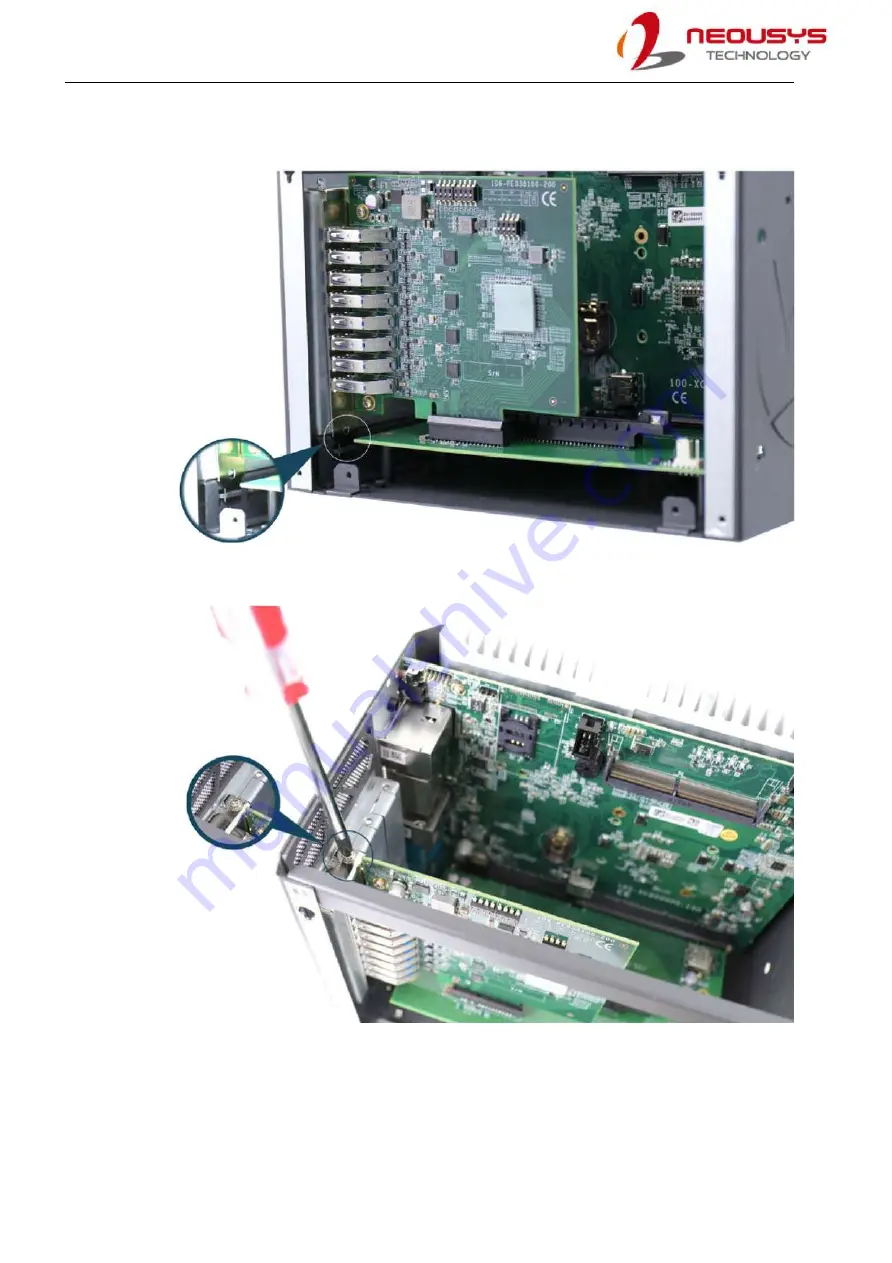
5.
Make sure the bottom of the PCIe card’s connector panel is properly inserted.
6.
Secure the PCIe-USB card to the chassis with a screw
7.
Reinstall the system’s chassis (panel) to complete the hardware installation process.
Страница 1: ...Neousys Technology Inc PCIe USB381F Frame Grabber Card User Manual Rev A1 0 ...
Страница 2: ... USB Card 11 2 2 Superior View 11 2 3 DIP Switch 1 and 2 Settings 12 2 4 DIP Switch 3 Settings 13 2 4 1 DIP Switch 3 13 2 4 2 Board ID Settings Via DIP Switch 3 14 3 PCIe USB Card Installation 3 1 Hardware Installation 15 3 2 Software Installation 17 Appendix A PCIe USB381F Function Library PCIe USB381F Library Installation 18 Using PCIe USB381F Function 21 PCIe USB381F Function Reference 21 UsbPo...
Страница 3: ... in advance with Neousys Technology Inc Customer is solely responsible for ensuring the compatibility and interoperability of the third party s products Customer is further solely responsible for ensuring its systems software and data are adequately backed up as a precaution against possible failures alternation or loss For questions in regards to hardware software compatibility customers should c...
Страница 4: ... New Taipei City 23586 Taiwan Tel 886 2 2223 6182 Fax 886 2 2223 6183 Email Website Americas Illinois USA Neousys Technology America Inc 3384 Commercial Avenue Northbrook IL 60062 USA Tel 1 847 656 3298 Email Website China Neousys Technology China Ltd Room 612 Building 32 Guiping Road 680 Shanghai Tel 86 2161155366 Email Website ...
Страница 5: ... trademarks of Intel Corporation NVIDIA GeForce are registered trademarks of NVIDIA Corporation All other names brands products or services are trademarks or registered trademarks of their respective owners FCC Conformity This equipment has been tested and found to comply with the limits for a Class A digital device pursuant to part 15 of the FCC Rules These limits are designed to provide reasonab...
Страница 6: ...r cords and other connection cables away from foot traffic Do not place items over power cords and make sure they do not rest against data cables Shutdown disconnect all cables from the system and ground yourself before touching internal modules Ensure that the correct power range is being used before powering the device Should a module fail arrange for a replacement as soon as possible to minimiz...
Страница 7: ...ly as possible while assuring proper connector engagement ESD Precautions Handle add on module motherboard by their retention screws or the module s frame heat sink Avoid touching the PCB circuit board or add on module connector pins Use a grounded wrist strap and an anti static work pad to discharge static electricity when installing or maintaining the system Avoid dust debris carpets plastic vin...
Страница 8: ...nd describes how to setup install Neousys Technology PCIe USB381F frame grabber card It offers connectivity expansion stability and SuperSpeed USB3 1 Gen1 performance to your existing system Revision History Version Date Description 1 0 Feb 2021 Initial release ...
Страница 9: ...381F are accessible on the faceplate for easy cabling Each port can deliver standard 900mA regulated 5V output to power USB3 0 cameras or user configurable 1800mA output via onboard jumpers for devices that require higher power consumption It also supports software programmable per port power on off control to reset cameras or other devices for fault recovery The steady 400 MB s data throughput sa...
Страница 10: ...ation Revision 2 0 USB3 Host Controller 4x Fresco FL1100SX host controllers compliant with Intel xHCI Specification Revision 1 0 Per Port Current Limit User configurable 900mA 1800mA per port current limit Power Requirement Maximal 2 0 A 3 3V from PCI Express bus Maximal 5 5 A 12V from PCI Express bus for all connected USB devices Operating Temperature 0 60 C with ambient airflow Dimension 117 7 m...
Страница 11: ...1F frame grabber card 1 2 Drivers Utilities Disc 1 2 2 Superior View Shown below is a PCIe USB381F frame grabber card from top to bottom they are channels 0 7 On the top DIP switches 1 and 2 are indicated in red they offer per port current configurable settings of 900mA or 1800mA Please refer to the DIP switch 1 and 2 settings for details To the right of DIP switches 1 and 2 you can find DIP switc...
Страница 12: ...1 P2 P3 P4 P5 P6 P7 P8 DIP switch 1 and 2 DIP switch settings The current output setting can be configured for each individual USB port The current output can be set at 900mA position or 1800mA position By default the If the DIP switches are set to output 900mA You may also set all channels to output 1800mA without any issue ...
Страница 13: ...designed for failure recovery in the field to rest connected devices To support per port on off control for multiple cards the PCIe USB381F card has DIP switch 3 indicated in blue to configure user defined board ID The board ID can be used as a parameter in API to specify the card 2 4 1 DIP Switch 3 There are four DIP switches but to configure the board ID you only need to configure the DIP switch...
Страница 14: ...PCIe USB381F 2 4 2 Board ID Settings Via DIP Switch 3 To set board IDs please refer to the following table Board ID DIP Switch 3 Position P1 P3 0 1 2 3 4 5 6 7 ...
Страница 15: ...e refer to the following procedure 3 1 Hardware Installation 1 Save and close all work in progress 2 Power off and unplug the power cable from the system you wish to install to 3 Open the chassis side panel of the computer you wish to install the PCIe USB card into 4 Locate a x4 PCIe or spare x16 PCIe slot remove the corresponding connector panel and gently lower the gold finger of PCIe USB381F in...
Страница 16: ...Make sure the bottom of the PCIe card s connector panel is properly inserted 6 Secure the PCIe USB card to the chassis with a screw 7 Reinstall the system s chassis panel to complete the hardware installation process ...
Страница 17: ...ure to take advantage of all the functions offered 1 Plug in the power cable and power up the system 2 Once you are in the system insert the driver disc included in the package into the DVD ROM 3 Execute the file FLUSB3 0 3 8 35514 0 exe it may be located in the directory x Driver_Pool USB3_Fresco Win7_ALL 4 For PCIe USB381F library please go to the following directory and execute the EXE file x D...
Страница 18: ... program the USB ports on PCIe USB381F Currently PCIe USB381F library supports the following operating systems Windows 7 32 bit 64 bit Windows 10 32 bit 64 bit For other OS support please contact Neousys Technology for further information PCIe USB381F Library Installation The PCIe USB381F function library is delivered in the form of a setup package named PCIeUSB381_Setup_v1 0 exe In prior to progr...
Страница 19: ...g related files The default directory is C Neousys PCIeUSB381 3 During the process the installation file may detect and prompt you to install other Microsoft components Please click on the I agree to the license terms and conditions and click on Install to continue ...
Страница 20: ...alog appears to prompt you to reboot the system The PCIe USB381F library will take effect after the system reboots 5 When you program your PCIe USB381F the related files are located in Header file Include Lib file Lib Function Reference Manual Sample Code Sample ...
Страница 21: ...ue Return Value Returns a negative integer value if function failed otherwise if function successes Usage if 0 UsbPort_Open 0 return false UsbPort_Close Syntax int __stdcall UsbPort_Close BYTE smtSwitch Description This function is used to release and cleanup the inner resources used by PCIe USB381F library Parameter in smtSwitch BYTE value that specifies the SMT switch of PCIe USB381F For current...
Страница 22: ...USB381F please always specify 0 for default value in portCtrl BYTE value that specifies a bit mask for power control of corresponding USB port A bit value of 0 indicates disabling the power for corresponding port and a bit value of 1 indicated enabling the power for corresponding port Return Value Returns a negative integer value if function failed otherwise if function successes Usage if 0 UsbPor...
Страница 23: ...CIe USB381F please always specify 0 for default value out pPortStatus Pointer to BYTE value that contains the bit mask of power status Each bit in pPortStatus indicates the on off status of corresponding USB port A bit value of 0 indicated power is disabled and a bit value of 1 indifcated power is enabled Return Value Returns a negative integer value if function failed otherwise if function succes...
Страница 24: ...sbPort_PowerStatus 0 portStatus if 0 result printf UsbPort_PowerStatus FAILED d n result return 2 printf UsbPort_PowerStatus PASSED n Step3 control the power disable port 0 2 4 6 portStatus 0xAA 10101010b result UsbPort_PowerControl 0 portStatus if 0 result printf UsbPort_PowerControl FAILED d n result return 3 printf UsbPort_PowerControl PASSED n Step4 close and release library resource result Us...