CHAPTER 4. OMNI DRIVE MODULE
4.3. MOUNTING
4.2.4 Safety Measures and Precautions
In order to ensure a safe and successful operation of the Omni-Drive-Module, please mind the following:
• Always take care to protect the drive amplifiers at the side of the module against collisions and moisture.
• Always lift the wheels off the ground while working on the control software.
• Always test any new or changed control software thoroughly with the wheels lifted off the ground. Make sure
that the alignment of all wheels is correct at all times and under all conditions.
• The wire diameter of the power supply to the Omni-Drive-Modules as well as any relays must be chosen ac-
cording to the maximum expected current.
Warning:
If three or more modules are used, very high sum currents might occur.
4.3 Mounting
4.3.1 Integrating the Module into a Platform
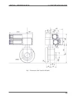
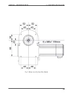
Six threaded holes in the bottom side of the Omni-Drive-Module can be used to mount the module onto a carrier plate.
The Omni-Drive-Module is not designed to be mounted under a vehicle but into it. The base plate of your vehicle
must be in between the wheel carrier assembly and the gearbox housing.
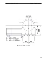
A U-shaped cut-out of 60 mm to 70 mm width is recommended for the vertical axle of the wheel carrier assembly.
4.3.2 Mounting Components onto the Module
If all Omni-Drive-Modules are mounted to a common base plate, additional components may be placed on top of the
modules. The step above the drive amplifiers can be used for mounting an auxiliary plate. This might be used to carry
smaller components, for example electronic devices.
Using a single plate on top of and screwed to all modules will significantly improve the structure of the overall drive
system. It will also optimise the distribution of forces thus allowing a high payload.
4.4 Electrical Installation
4.4.1 Power Supply
4.4.1.1 Main Power
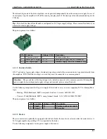
Both drive amplifiers are connected to common supply lines. Use the following components for the power supply:
• Plug: Würth Elektronik, Series 351 WR-TBL, 691 351 500 003
• Plug (alternative): Phoenix Contact, MSTB 2,5 HC/ 3-ST, 1911868
• Power cable: H07V-K or better, 2,5 mm
2
or bigger
• Logic supply cable: H05V-K or better, 0,5 mm
2
or bigger
47
Содержание MMO-700
Страница 1: ...MMO 700 Neobotix GmbH Apr 14 2022 ...
Страница 11: ...CHAPTER 1 MMO 700 1 6 TRANSPORT Fig 3 Position of the auxiliary batteries and battery connectors 7 ...
Страница 33: ...CHAPTER 3 GENERAL HARDWARE INFORMATION 3 4 CHARGING STATIONS Fig 2 Position of the main power switch X 29 ...
Страница 52: ...CHAPTER 4 OMNI DRIVE MODULE 4 4 ELECTRICAL INSTALLATION Fig 1 Dimensions of the Omni Drive Module 48 ...
Страница 53: ...CHAPTER 4 OMNI DRIVE MODULE 4 4 ELECTRICAL INSTALLATION Fig 2 Bottom view of the Omni Drive Module 49 ...
Страница 54: ...CHAPTER 4 OMNI DRIVE MODULE 4 4 ELECTRICAL INSTALLATION Fig 3 Top view of the Omni Drive Module 50 ...

