background image


NEMIC-LAMBDA


SWS 

50

75

100

150 

Series


INSTRUCTION MANUAL


3. Explanation of Functions and Precautions 

3-1. Input Voltage Range 

Input voltage range is single phase 85 ~ 265VAC ( 47 ~ 
63Hz ) or 120 ~ 330VDC. Input voltage which is out of 
specification may cause unit damage.For cases where con-
formance to various safety specs(UL,CSA,EN) are re-
quired,input voltage range will be 100~240VAC ( 50/60Hz ). 

3-2. Output Voltage Range 

V.ADJ trimmer is for output voltage adjustment within the 
range of specifications.To turn the trimmer clockwise, the 
output voltage will be increased. Note over voltage protec-
tion ( OVP ) function may trigger if the output voltage is in-
creased excessively. 

3-3. Inrush Current 

Power Thermistor is built in to protect the circuit from In-
rush Current. Please carefully select input switch and fuse in 
cases of the high temperature and re-input the power. 

3-4. Over Voltage Protection (OVP) 

The OVP function ( Inverter shut down method, manual re-
set type ) is provided. When OVP triggers, the output will be 
shut down. The input shall be removed for a few minutes, 
and then re-input for recovery of the output. OVP setting is 
fixed and not to be adjusted externally. 

3-5. Over Current Protection (OCP) 

Current limiting, automatic recovery. OCP function operates 
when the output current exceeds OCP specifications. The 
output will be automatically recovered when the overload 
condition is canceled. Do not operate overload or dead short 
conditions for more than 30 seconds, which could result in 
damage or insulation failure. 
 

3-6. Output Ripple & Noise 

Ripple & noise are measured at 20MHz by using a 12’’ 
twisted pair terminated with a 0.1uF & 47uF capacitor. 
When load lines are longer, ripple will become larger. In this 
case, electrolytic capacitor, film capacitor, etc. might be nec-
essary to use across the load terminal. The output ripple 
cannot be measured accurately if the probe ground lead of 
oscilloscope is too long. 


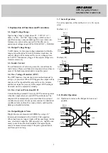
3-7. Series Operation 

For series operation, either method ( A ) or ( B ) is pos-
sible. 
 
Method ( A ) 

O utput
Terminal

O utput
Terminal

Load

P ower
Supply


Method ( B ) 

Power
Supply

Load

Load

Output
Terminal

Output
Terminal


3-8. Parallel Operation 

(A)  Operation to increase the Output Current is not 

possible. 


Load 

Output 

Terminal

Output 

Terminal

Power 

Supply 


Содержание SWS50 Series

Страница 1: ...osed in other equipment Stick the WARNING label for users on the system equipment and describe the notice in the instruction manual Never operate the unit under over current or shorted conditions for 30 seconds or more and out of Input volt age range in specification which could result in damage or insulation failure There is no possibility for fire or burning Confirm connections to input output t...

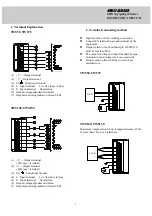
Страница 2: ... L Input terminal Live line Fuse in line 5 N Input terminal Neutral line 6 Output voltage adjustment trimmer 7 Output monitoring indicator Green LED 2 Terminal connecting method Input must be off when making connection Connect FG terminal to ground terminal of the equipment Output current of each terminal pin of SWS150 must be less than 20A The output load line and input line shall be sepa rated a...

Страница 3: ...The input shall be removed for a few minutes and then re input for recovery of the output OVP setting is fixed and not to be adjusted externally 3 5 Over Current Protection OCP Current limiting automatic recovery OCP function operates when the output current exceeds OCP specifications The output will be automatically recovered when the overload condition is canceled Do not operate overload or dead...

Страница 4: ...0kVAC between input and FG chassis and 500VAC between output and FG chassis each for 1 min ute When testing withstand voltage set current limit of withstand voltage test equipment at 20mA Output FG chassis 100mA The applied voltage must be gradually increased from zero to testing value and then gradually de creased for shut down When timer is used the power supply may be damaged by high impulse vo...

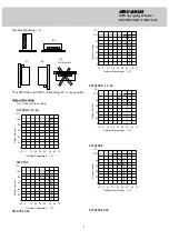
Страница 5: ...put Current A B C D SWS75 5 100 10 0 10 20 30 40 50 60 70 80 60 40 20 0 Ambient Temperature C Output Current A B C D SWS75 12 24 100 10 0 10 20 30 40 50 60 70 80 60 40 20 0 Ambient Temperature C Output Current A B C D SWS100 5 12 24 100 10 0 10 20 30 40 50 60 70 80 60 40 20 0 Ambient Temperature C Output Current A B C SWS150 5 100 10 0 10 20 30 40 50 60 70 80 60 40 20 0 Ambient Temperature C Outpu...

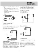
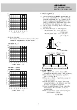
Страница 6: ...e units please make sure to place them 15mm or more apart from each other 2 The maximum allowable penetration of mounting screws is 6mm 3 Recommended torque for mounting screw SWS50 SWS75 M3 screw 0 49 N m 5 0 kgf cm SWS100 SWS150 M4 screw 1 27 N m 13 0 kgf cm 6 Wiring Method The output load line and input line shall be separated and twisted to improve noise sensitivity Use all lines as thick and ...

Страница 7: ...0 SWS100 3 15A SWS75 SWS150 5A 8 Before concluding that the unit is at fault Before concluding that the unit is at fault make the follow ing checks Check if the rated input voltage is connected Check if the wiring of input and output is correct Check if the wire material is not too thin Check if the output voltage control V ADJ is properly adjusted Check if the output current and output wattage do...

Отзывы: