1
NEMIC-LAMBDA
SWS
50
⋅
75
⋅
100
⋅
150
Series
INSTRUCTION MANUAL
1. Terminal Explanation
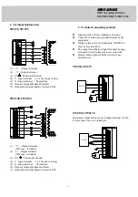
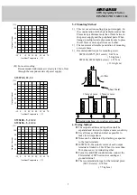
SWS50,
SWS75
(1) +V : + Output terminal
(2) - V : - Output terminal
(3) FG
: Functional Ground
(4) L : Input terminal Live line (Fuse in line)
(5) N : Input terminal Neutral line
(6) Output voltage adjustment trimmer
(7) Output monitoring indicator (Green LED)
SWS100,
SWS150
(1) +V : + Output terminal
( 20A max./ terminal)
(2) -V : - Output terminal
( 20A max./ terminal)
(3) FG
: Functional Ground
(4) L : Input terminal Live line(Fuse in line)
(5) N : Input terminal Neutral line
(6) Output voltage adjustment trimmer
(7) Output monitoring indicator (Green LED)
2. Terminal connecting method
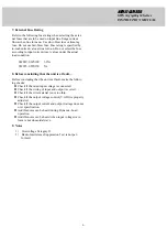
Input must be off when making connection.
Connect FG terminal to ground terminal of the
equipment.
Output current of each terminal pin of SWS150
must be less than 20A.
The output load line and input line shall be sepa-
rated and twisted to improve noise sensitivity.
Remote sensing lines shall be twisted or use
shielded wire.
SWS50, SWS75
LOAD
+
-
SWS100, SWS150
Maximum output current of each output terminal is 20A.
If more than 20A, use 2 terminals.
+
-
LOAD


