
33
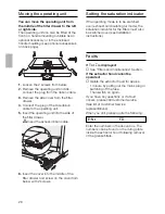
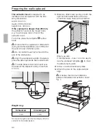
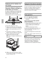
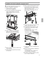
1.
Disconnect from power.
2.
Disconnect pipes.
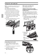
3.
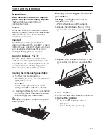
Remove filters.
4.
Undo right and left fixing screws until the
extractor hood cannot drop any further.
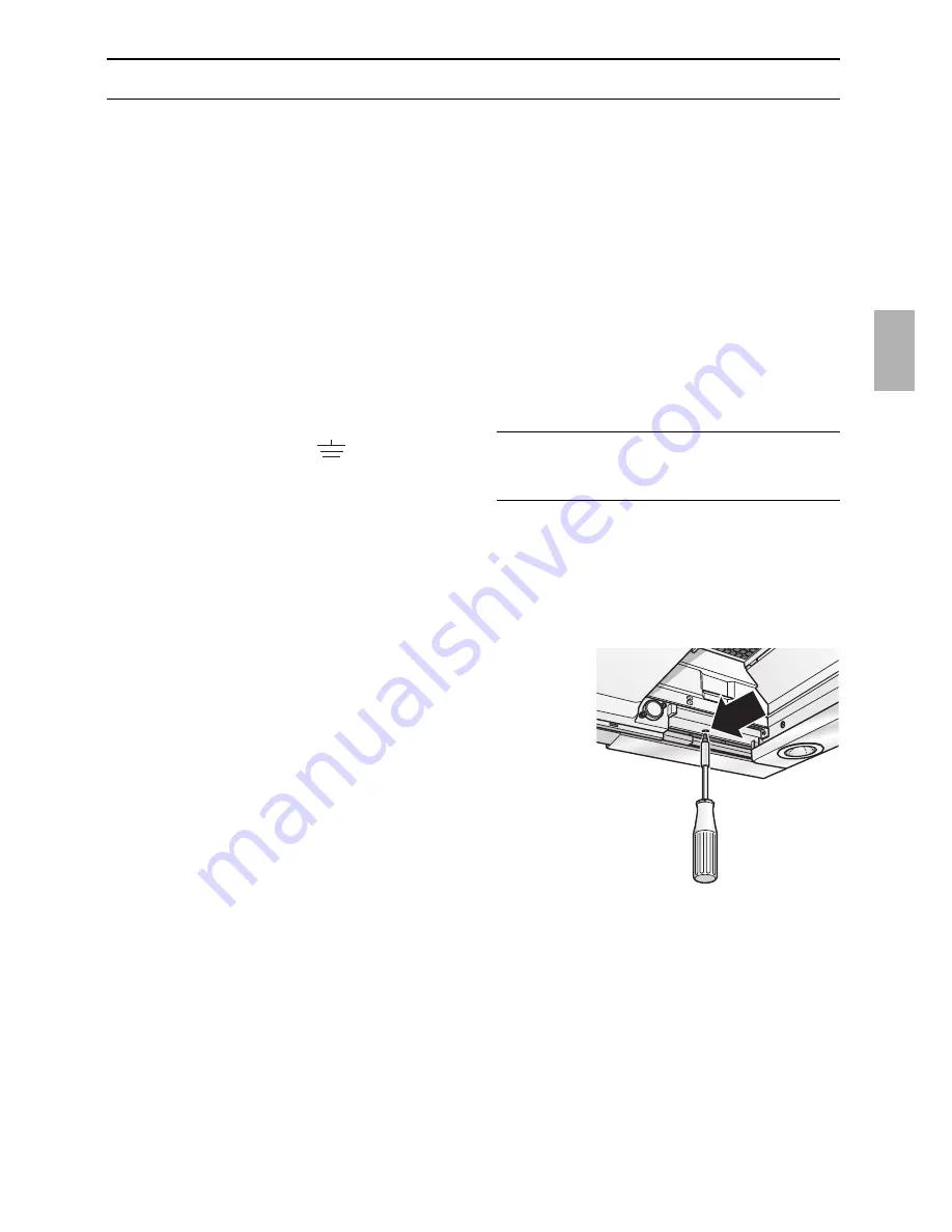
5.
Raise the extractor hood briefly until the
fixing lugs detach and the appliance can
be lowered.
Fastening screws may project.
When raising the extractor hood, do not
force in the filter drawer.
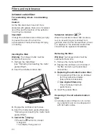
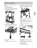
6. Preparing for re-installation:
Screw in the left and right fixing screws
until the lugs are pressed out at the
sides.
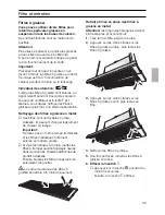
Electrical connection
WARNING: THIS APPLIANCE MUST BE
EARTHED
IMPORTANT: Fitting a Different Plug:
The wires in the power cord are colour-
coded as follows:
Green and Yellow
– Earth
Blue
– Neutral
Brown
– Live
If you fit your own plug, the colours of
these wires may not correspond with the
identifying marks on the plug terminals.
Proceed as follows:
1.
Connect the green and yellow (Earth)
wire to the terminal in the plug marked
‘E’ or with the symbol ( ), or
coloured green or green and yellow.
2.
Connect the blue (Neutral) wire to the
terminal in the plug marked ‘N’ or
coloured black.
3.
Connect the brown (Live) wire to the
terminal marked ‘L’, or coloured red.
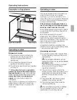
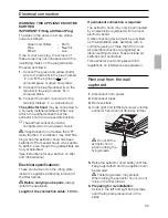
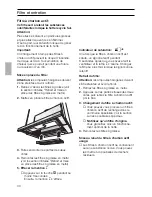
The extractor hood
may be connected to
a correctly installed earthed socket only.
Attach the earthed socket near the
extractor hood in an accessible position.
❑
The earthed socket should be
connected via its own power circuit.
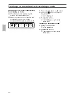
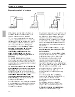
If appliances do not feature the OFF
delay function, the indicator may start flas-
hing when the extractor hood has been
switched off for several hours via a separa-
te switch, even though the grease filters are
not yet saturated.
(See instructions for use, section on filter
and maintenance).
Electrical specifications:
These can be found on the rating plate
inside the appliance following removal of
the filter frames.
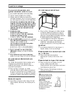
Before carrying out repairs,
always
isolate the appliance.
Length of the connection cable: 1.30 m.
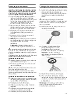
If permanent connection is required:
The extractor hood may only be connected
by an electrician registered with the local
electricity board.
A disconnecting device must be provided
on the installation side. Switches with a
contact opening of more than 3 mm and
all-pole disconnection are regarded as
disconnecting devices. These include LS
switches and contactors.
This extractor hood complies with EU
regulations on interference suppression.
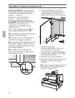
Removal from the wall
cupboard
Do not lift the
extractor hood
when undoing the
fixing screws.
Содержание DA89B
Страница 99: ...99 D 4 Pa 0 04 mbar...
Страница 100: ...100 T E A...
Страница 101: ...101 L 1 10 2 off on On Off On Off 5 55...
Страница 102: ...102 2 L 10 a a 3 3...
Страница 103: ...103 1 2 4 5 6 L 3 3 6...
Страница 104: ...104 A 1 2 3 4 3 4 5 L 3 6 1 2...
Страница 105: ...105 3 12 Volt 20 Watt G4 4 5 1 2...
Страница 106: ...106 1 2 2 3 4 5 6 2 1 FD...
Страница 107: ...107 650 mm 1 Hs 03 0 kW 08 3 kW 03 9 kW 03 9 kW 11 3 kW 430 mm 1 TRGI 300 mm...
Страница 108: ...108 D D 4 Pa 0 04 mbar...
Страница 109: ...109 150 mm 120 mm 150 mm l 120 mm 113 cm2 l 150 mm 177 cm2 1 O I 2 270 mm 900 mm l 150 mm l 120 mm...
Страница 110: ...110 600 mm 293 350 mm 435 mm 293 mm O II 0 5 mm 1 l 2 mm 10 mm O II 2 3 1...
Страница 111: ...2 7 8 9 1 2 5 2 6 4 2 111...
Страница 112: ...112 2 1 O III l 2 mm 10 mm 16 0 16 5 kg...
Страница 113: ...113 1 2 3 4 1 30 m 3 mm LS 5 6 1 2 3 2...
Страница 114: ...114 1 L 2 3 3 1 2...
Страница 115: ...115 Z5144X5 434229 Aluminium Z5779A0 Metall Z5779N0 1 3 4 2 5 3x Aluminium Z5789A0 Metall Z5789N0...


