Trolley Return Unit 920/1500
27
EN
9
Troubleshooting
Table 9-1: Troubleshooting table
Cause
Solution
The system does not react to
any activity.
Check that the working switch is switched on and that the power fuse is
intact. Measure the power supply after the working switch. Check that
the fuse F1/ 2 or 4 A time lag T is intact and that the power supply can
be measured after the fuse. Also check the transformer voltage setting
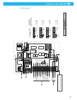
according to Circuit diagram 1.
The fan does not start when the
suction hose is lowered.
Pull the suction trolley from connection position: if the fan still does not
start, search for a short circuit in SLX1 (disconnection arrow). If the fan
starts, search for a short circuit in SLX (limit position on suction trolley).
Check that fuse (F2/ 2AT) is intact. Check that there is 24 VAC power
supply.
The Drive motor does not start.
Check that the fuse F 10 AT is intact. The fuse is located on the control
board in the Drive unit. Check the emergency stop. Contact K1 is off when
the emergency stop is depressed. Measure the voltage on K1 to the drive
motor 15 - 24 VDC.
The Drive motor starts but stops
after 3 seconds.
Check limit switch SL4: release SL4 from the stop ball and measure on
the wires when SL4 is unaccuated. If SL4 is closed when unaccuated,
(SL4 is open when unaccuated and closed when accuated), then search
for a mechanical or electrical fault in the limit switch or a short circuit in
the wires.
The Drive motor does not stop
after passing the limit switch
SL4.
Limit switch SL4 circuit is defective. Open circuit in switch or cabling.
Action: Allow the drive motor to run approximately 120 seconds until it
stops. If the suction trolley is in connection position, pull out the trolley
so that you release the driving slot from the disconnection arrow and
then press the start button. Drive motor starts and will pull the suction
trolley into connection position. After this manoeuvre SLX and SLX1 have
taken over the function of SL4 to stop the drive motor and the system can
continue to run until the fault can be corrected.
Содержание 920/1500
Страница 2: ...Trolley Return Unit 920 1500 2 ...
Страница 3: ...Trolley Return Unit 920 1500 3 English 4 ...
Страница 28: ...Trolley Return Unit 920 1500 EN 28 Appendix A Cable connections Cable connections overview ...
Страница 29: ...Trolley Return Unit 920 1500 29 EN Simple cable connections overview ...
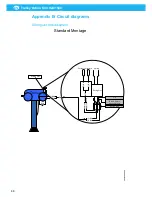
Страница 30: ...Trolley Return Unit 920 1500 EN 30 Appendix B Circuit diagrams Driving slot circuit diagram ...
Страница 31: ...Trolley Return Unit 920 1500 31 EN Circuit diagram 1 ...
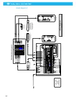
Страница 32: ...Trolley Return Unit 920 1500 EN 32 Circuit diagram 2 ...
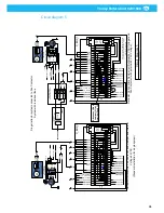
Страница 33: ...Trolley Return Unit 920 1500 33 EN Circuit diagram 3 ...
Страница 34: ...Trolley Return Unit 920 1500 EN 34 Circuit diagram 4 ...
Страница 35: ...Trolley Return Unit 920 1500 35 EN Circuit diagram 5 ...
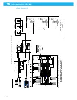
Страница 36: ...Trolley Return Unit 920 1500 EN 36 Circuit diagram 6 ...
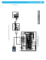
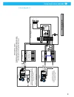
Страница 37: ...Trolley Return Unit 920 1500 37 EN Circuit diagram 7 ...
Страница 38: ...Trolley Return Unit 920 1500 EN 38 Circuit diagram 8 ...
Страница 39: ...Trolley Return Unit 920 1500 39 EN Circuit diagram 9 ...
Страница 40: ...Trolley Return Unit 920 1500 EN 40 Circuit diagram 10 ...
Страница 41: ......
Страница 42: ......
Страница 43: ......
Страница 44: ...www nederman com ...


