Trolley Return Unit 920/1500
EN
24
5.5
Installation checking
WARNING!
Risk of electric shock!
Work with electric equipment is to be carried out by a qualified electrician. A lockable
safety switch shall be installed between the system and the power network.
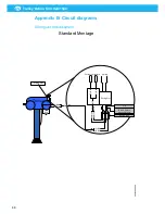
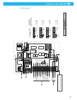
First check the Drive unit fuse set up and transformer voltage setting according to
Appendix B, ‘Circuit diagram 1’.
Connect the system to the power network.
•
Connect cable W13 to Drive unit and Safety switch according to Appendix B,
‘Circuit diagram 1’ and Appendix A, ‘Cable connections overview’.
•
Connect cable W14 and W15 to Fan Starter or Fan Inverter and Safety switch
according to Appendix A, ‘Cable connections overview’ and Fan control equipment
documentation.
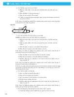
Operate the system and check that the wire moves in the correct direction. If this is
not the case, shift the motor cable wires (blue and black) on the contactor K1, see
Appendix B, ‘Circuit diagram 1’.
NOTE!
Check the following points after installation
•
Check that the motor damper opens and the fan starts:
–
When the suction trolley is in connection position (Suction trolley is connected
to Disconnection arrow) ready for use and the hose is pulled down to be
connected to the vehicle’s exhaust pipe.
–
When the suction trolley is pulled from the disconnection arrow.
•
Check that the motor damper closes, or the fan stops:
–
When the carbon brushes are inside the bus bar and the hose is in raised position
(activated Limit switch).
–
When the start button on the Control box has been activated (trolley return
activated).
•
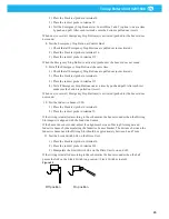
Check the wire tension as follows
–
See point 28:
–
Too high wire tension: Check the return time for the suction trolley’s return. For
35 m rail it should be about 50 seconds. A longer time may mean that the wire is
tensioned too much.
–
Too low wire tension: Check the wire tension by slowing the suction trolley
manually during return. Check that the wire does not slip on the motor unit’s
drive wheel. The motor protection should be triggered after some time
–
Either too high or too loose wire tension causes excessive wear to the drive
pulley rubber.
NOTE!
Note that the wire tension may need to be adjusted depending on various
environmental and operational conditions.
•
Check that the suction trolley’s parking position is correct in relation to the vehicle’s
set-up location.
•
Check that the control boxes operate both in manual and automatic mode.
•
Check that the inductive sensor SL2 is fitted in such a position that it produces a
signal and slows down the suction trolley to a suitable speed before it stops against
the exhaust rail’s internal end stop.
•
Check the signal function for the whole length of the bus bar. If necessary, adjust in
accordance with the installation instructions, point 34.
Содержание 920/1500
Страница 2: ...Trolley Return Unit 920 1500 2 ...
Страница 3: ...Trolley Return Unit 920 1500 3 English 4 ...
Страница 28: ...Trolley Return Unit 920 1500 EN 28 Appendix A Cable connections Cable connections overview ...
Страница 29: ...Trolley Return Unit 920 1500 29 EN Simple cable connections overview ...
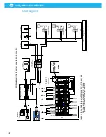
Страница 30: ...Trolley Return Unit 920 1500 EN 30 Appendix B Circuit diagrams Driving slot circuit diagram ...
Страница 31: ...Trolley Return Unit 920 1500 31 EN Circuit diagram 1 ...
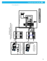
Страница 32: ...Trolley Return Unit 920 1500 EN 32 Circuit diagram 2 ...
Страница 33: ...Trolley Return Unit 920 1500 33 EN Circuit diagram 3 ...
Страница 34: ...Trolley Return Unit 920 1500 EN 34 Circuit diagram 4 ...
Страница 35: ...Trolley Return Unit 920 1500 35 EN Circuit diagram 5 ...
Страница 36: ...Trolley Return Unit 920 1500 EN 36 Circuit diagram 6 ...
Страница 37: ...Trolley Return Unit 920 1500 37 EN Circuit diagram 7 ...
Страница 38: ...Trolley Return Unit 920 1500 EN 38 Circuit diagram 8 ...
Страница 39: ...Trolley Return Unit 920 1500 39 EN Circuit diagram 9 ...
Страница 40: ...Trolley Return Unit 920 1500 EN 40 Circuit diagram 10 ...
Страница 41: ......
Страница 42: ......
Страница 43: ......
Страница 44: ...www nederman com ...


