NDA-24232 Issue 2.0
Page 2-1
VisuaLink 128/384 Quick Installation Guide
Chapter 2
Chapter 2 VisuaLink Stand-Alone System
2.1 Connection of the
Surrounding
Devices
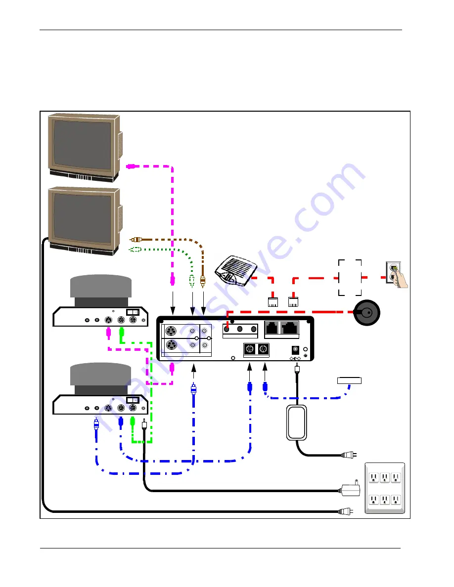
This section gives a description on how to setup a VisuaLink as a stand-alone
system. In Figure 2-1, the VisuaLink 128 shows a VoicePoint.
Figure 2-2
shows
the VisuaLink 384 components. All the components shown in the drawing are
optional
.
Figure 2-1: VisuaLink 128 System Connections
+
+
+
+
+
DC IN 5V
+
-
Serial1 Serial2/RMT
O
U
T
I
N
VIDEO2 VIDEO1 AUDIO
+
+
TEL S/T LINE
MIC1 MIC2 MIC3
AC
AC
VisuaLink 128
Monitor 1
VoicePoint
AC POWER
STRIP
Microphone
PC Terminal
Camera 1
Video
Audio
S Video
IN VISCA OUT
Power
ON
OFF
MIC
NT1
Monitor 2
Camera 2
Video
Audio
S Video
IN VISCA OUT
Power
ON
OFF
MIC
S/T
U
Interface
Interface
Содержание VisuaLink 128
Страница 6: ......
Страница 54: ...Page 6 8 NDA 24232 Issue 2 0 Chapter 6 VisuaLink Quick Installation Guide This page is for your notes ...
Страница 58: ...Page A 4 NDA 24232 Issue 2 0 Appendix A VisuaLink 128 384 Quick Installation Guide This page is for your notes ...
Страница 62: ...Page B 4 NDA 24232 Issue 2 0 Appendix B VisuaLink 128 384 Quick Installation Guide This page is for your notes ...


