background image

E-20

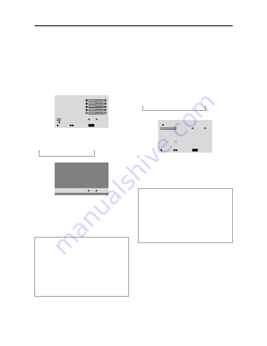
Reducing noise in the picture

Use these settings if the picture has noise due to poor
reception or when playing video tapes on which the picture
quality is poor.

Example: Setting “NR-3”

Press the MENU/ENTER button on the remote control to
display the MAIN MENU on the screen, then...

1. Use the 

 and 

 buttons to select “PICTURE”, then

press the MENU/ENTER button.
The “PICTURE” screen appears.

2. Use the 

 and 

 buttons to select “NR”.

PICTURE

1 / 2

EXIT

CONTRAST

BRIGHTNESS

SHARPNESS

COLOR

TINT

PICTURE MODE

NR

        NEXT PAGE

:     NORMAL

:     

OFF

SEL.

RETURN

ADJ.

3. Use the 


 and  

 buttons to select “NR-3”.

The mode switches as follows when the 

 and 

buttons are pressed:

 OFF 

 NR-1 

 NR-2 

 NR-3 

NR

:     

NR-3

* If neither the 

 or 

 button is pressed within 5 seconds,

the current selection is set and the previous screen
reappears.

4. Once the setting is completed ...

Press the EXIT button to return to the main menu.
To delete the main menu, press the EXIT button once
more.

Information

 NR

* “NR” stands for Noise Reduction.
* This function reduces noise in the picture.

 Types of noise reduction

There are three types of noise reduction. Each has a
different level of noise reduction.
The effect becomes stronger as the number increases
(in the order 

NR-1 

 NR-2 

 NR-3

).

OFF ...............

Turns the noise reduction function off.

Setting the color temperature

Use this procedure to set color tone produced by the plasma
display.

Example: Setting “HIGH”

Press the MENU/ENTER button on the remote control to
display the MAIN MENU on the screen, then...

1. Use the 

 and 

 buttons to select “PICTURE”, then

press the MENU/ENTER button.
The “PICTURE” screen appears.

2. Use the 

 and 

 buttons to select “COLOR TEMP.”.

3. Use the 

 and 

 buttons to select “HIGH”.

The mode switches as follows when the 

 and 

buttons are pressed:

 LOW 

 MID LOW 

 MID 

 HIGH 

* See below to set “WHITE BALANCE”.

PICTURE

2 / 2

EXIT

        PREVIOUS PAGE

COLOR TEMP.

GAMMA

LOW TONE

COLOR TUNE

:     

HIGH

:     2

:     AUTO

SEL.

RETURN

ADJ.

* If neither the 

 or 

 button is pressed within 5 seconds,

the current selection is set and the previous screen reappears.

4. Once the setting is completed...

Press the EXIT button to return to the main menu.
To delete the main menu, press the EXIT button once
more.

Information

 Setting the color temperature

LOW ................

Redder

MID LOW

......... Slightly redder

MID

................... Standard (slightly bluer)

HIGH ...............

Bluer

 Restoring the factory default settings

Select “ALL RESET” under the OPTION1 menu. Note
that this also restores other settings to the factory defaults.

Adjusting the color to the desired level

Use this procedure to adjust the white balance for each
color temperature to achieve the desired color quality.

Example: Adjusting the “GAIN RED” of “HIGH” color
temperature

Set “ADVANCED OSM” to “ON” in the main menu (1/
2), then perform the following operations.

Press the MENU/ENTER button on the remote control to
display the MAIN MENU on the screen, then...

Perform Steps 1-3 of COLOR  TEMP., then...

4. Press the MENU/ENTER button.

The “WHITE BALANCE” screen appears.

3-83

CONFIDENTIAL

Содержание PlasmaSync 42VP4 (42Wide VGA)

Страница 1: ...s Manual Bedienungshandbuch Manuel de l utilisateur Manual del Usuario Manuale d uso Bruksanvisning maSync 42VP4 42VP4D 42Wide VGA PX 42VP4G 42VP4DG PlasmaSync 42XM2 42XGA PX 42XM2G PlasmaSync 50XM3 50XGA PX 50XM3G 3 59 CONFIDENTIAL ...

Страница 2: ...User s Manual Bedienungshandbuch Manuel de l utilisateur Manual del Usuario Manuale d uso Bruksanvisning 3 60 CONFIDENTIAL ...

Страница 3: ...ine picture elements cells with more than 99 99 percent active cells There may be some cells that do not produce light or remain lit For operating safety and to avoid damage to the unit read carefully and observe the following instructions To avoid shock and fire hazards 1 Provide adequate space for ventilation to avoid internal heat build up Do not cover rear vents or install the unit in a closed...

Страница 4: ...lvents such as alcohol or thinner to clean these surfaces 2 Clean plasma ventilation areas with a vacuum cleaner with a soft brush nozzle attachment 3 To ensure proper ventilation cleaning of the ventilation areasmustbecarriedoutmonthly Morefrequentcleaning maybenecessarydependingontheenvironmentinwhich the plasma monitor is installed Recommendations to avoid or minimize phosphor burn in Like all ...

Страница 5: ...19 Reducing noise in the picture E 20 Setting the color temperature E 20 Adjusting the color to the desired level E 20 Changing the gamma curve E 21 Making the low tone adjustments E 21 Adjusting the colors E 22 Audio Settings Menu E 22 Adjusting the treble bass and left right balance and audio input select E 22 Setting the allocation of the audio connectors E 23 Image Adjust Settings Menu E 23 Ad...

Страница 6: ... own Be sure to use a stand or original mounting unit Wall mount unit Stand etc See page E 2 For correct installation and mounting it is strongly recommended to use a trained authorized dealer Failure to follow correct mounting procedures could result in damage to the equipment or injury to the installer Product warranty does not cover damage caused by improper installation Ventilation Requirement...

Страница 7: ...mpatibility NTSC PAL SECAM composite and S Video signal compatibility 480P 1080I 720P and HDTV signal compatibility PCs VCRs Laser Disc and DVD player source compatibility AccuBlend scan conversion automatically converts VGA SVGA XGA SXGA and UXGA signals to the panel s native resolution except for 42VP4 42VP4D except for 42XM2 Advanced Mass Area Sampling Progressive Scan method is employed RGB 3 ...

Страница 8: ...TSELECT DOWN UP LEFT RIGHT EXIT VOLUME POWER STANDBY 4 5 6 7 1 3 2 t LEFT and RIGHT Enlarges or reduces the image Functions as the CURSOR buttons in the On Screen Menu OSM mode y VOLUME DOWN and UP Adjusts the volume Functions as the CURSOR buttons in the On Screen Menu OSM mode u MENU ENTER Sets the On Screen Menu OSM mode and displays the main menu BNC INPUT RGB COMP SCART1 2 D SUB INPUT RGB SCA...

Страница 9: ...put can be used for Input or Output see page E 11 H RGB3 DVI 24pin Connect a digital signal TMDS from a source with a DVI output see page E 9 I EXTERNAL CONTROL This terminal is used when operating and controlling the monitor externally by RS 232C J REMOTE IN Connect the remote cable to the remote control s remote jack to obtain wired remote control K REMOTE OUT Connect the remote cable to the REM...

Страница 10: ...VIDEO as the source VIDEO can also be selected using the INPUT SELECT button on the monitor t MENU ENTER Press this button to access the OSM controls Press this button during the display of the main menu to go to the sub menu y CURSOR Use these buttons to select items or settings and to adjust settings or switch the display patterns u EXIT Press this button to exit the OSM controls in the main men...

Страница 11: ...he superimposed caption displayed fully only when the picture contains dark areas above and below the picture 8 ID SELECT Set the ID number in the remote control The remote control can then be used only for a display with the same ID number When several displays are used together they can be controlled individually 9 CLEAR Clears the number set by the ID SELECT button 0 Remote control signal trans...

Страница 12: ...ght or if there is an obstacle between the sensor and the remote control Handling the remote control Do not drop or mishandle the remote control Do not get the remote control wet If the remote control gets wet wipe it dry immediately Avoid heat and humidity When not using the remote control for a long period remove the batteries Do not use new and old batteries together or use different types toge...

Страница 13: ...e DVD1 or DVD2 terminals For SCART this unit provides three ways to connect SCART1 Connect R G B to the DVD2 terminals and composite sync to the HD terminal SCART2 Connect R G B to the DVD2 terminals and composite sync to the VIDEO1 terminal SCART3 Connect R G B composite sync to the RGB1 terminal Note This plasma monitor has the capasity to display images when connected to European DVD players wi...

Страница 14: ... DVI connector of the main unit NotethattheRGB3 DVI terminaldoesnotsupportanalog RGB input source Note 1 Input TMDS signals conforming to DVI standards The TMDS input corresponds to 1 link 2 To maintain display quality use a cable with a quality prescribedbyDVIstandardsthatiswithin5metersinlength Connecting Your Document Camera You can connect your plasma monitor to a document camera To do so simp...

Страница 15: ...tion Bi directional DATA SDA Horizontal sync or Composite sync Vertical sync Data clock Pin No 1 2 3 4 5 6 7 8 9 10 11 12 13 14 15 1 2 3 4 5 6 7 8 9 10 11 12 13 14 15 16 20 19 18 17 21 22 23 24 RGB 3 Pin No 1 2 3 4 5 6 7 8 9 10 11 12 13 14 15 16 17 18 19 20 21 22 23 24 Signal Digital T M D S Data 2 T M D S Data 2 T M D S Data 2 Shield No connection No connection DDC Clock DDC Data No connection T ...

Страница 16: ...ticularly recommended when using a 9 screen video wall From the second monitor onward connections require a BNC RCA conversion cable or connector a mini D Sub 15 pin cable BNC 5 cable or a conversion connector Creating a video wall With buit in matrix display capability you can create a 2 2 or 3 3 video wall Connect signal cables and remote cables as shown below Video signal RGB DVD HD signal VIDE...

Страница 17: ...ch time the DISPLAY button is pressed 2 If the button is not pressed for approximately three seconds the menu turns off DIGITAL ZOOM Digital zoom specifies the picture position and enlarges the picture 1 Press the POINTER button to display the pointer To change the size of the picture Press the ZOOM button and enlarge the picture The pointer will change to resemble a magnifying glass A press of th...

Страница 18: ...een set press the OFF TIMER button once 2 The remaining time is displayed then turns off after a few seconds 3 When five minutes remain the remaining time appears until it reaches zero OFF TIMER 28 To cancel the off timer 1 Press the OFF TIMER button twice in a row 2 The off timer is canceled OFF TIMER 0 Note After the power is turned off with the off timer A slight current is still supplied to th...

Страница 19: ...in the horizontal direction Images compressed in the horizontal direction squeezed images are expanded in the horizontal direction and displayed on the entire screen with correct linearity Normal images are expanded in the horizontal direction STADIUM size screen The picture is expanded in the horizontal and vertical directions at different ratios Use this for watching normal video programs 4 3 wi...

Страница 20: ...ring to the Table of Signals Supported on page E 43 IBM PC AT and VGA are registered trademarks of IBM Inc of the United States Wide Screen Operation with Computer Signals Switch to the wide screen mode to expand the 4 3 image to fill the entire screen 1 Press the WIDE button on the remote control 2 Within 3 seconds Press the WIDE button again The screen size switches as follows NORMAL FULL ZOOM N...

Страница 21: ...control to highlight the menu you wish to enter 3 Press the MENU ENTER button on the remote control to select a submenu or item PICTURE 1 2 EXIT CONTRAST BRIGHTNESS SHARPNESS COLOR TINT PICTURE MODE NR NEXT PAGE NORMAL OFF SEL RETURN ADJ 4 Adjust the level or change the setting of the selected item by using the cursor buttons on the remote control OSM On Screen Menu Controls 5 The adjustments or t...

Страница 22: ...y default values OFF Yes Main menu Sub menu Functions Default Reset AUDIO BASS Sets the bass Center Yes TREBLE Sets the treble Center Yes BALANCE Sets the left right balance Center Yes AUDIO INPUT1 3 Sets the allocation of the audio connectors 1 Yes Main menu Sub menu Functions Default Reset IMAGE ADJUST ASPECT MODE Selects between the different aspect ratio modes V POSITION Adjusts the vertical p...

Страница 23: ...trol ON Yes LOOP OUT When set to ON the received signal will be looped out OFF Yes ID NUMBER Sets ID number for the display ALL Yes VIDEO WALL DIVIDER Creates a 2 2 or 3 3 video wall OFF Yes POSITION Sets the position DISP MODE Selects the screen mode from between Splitting and Blanking SPLIT Yes AUTO ID Automatically sets the ID number of multiple displays OFF Yes IMAGE ADJUST Adjusts the positio...

Страница 24: ...signal is connected Restoring the factory default settings Select DEFAULT under the PICTURE MODE settings Setting the picture mode according to the brightness of the room There are four picture modes that can be used effectively according to the environment in which you are viewing the display Example Setting the THEAT 1 mode Press the MENU ENTER button on the remote control to display the MAIN ME...

Страница 25: ...isplay Example Setting HIGH Press the MENU ENTER button on the remote control to display the MAIN MENU on the screen then 1 Use the and buttons to select PICTURE then press the MENU ENTER button The PICTURE screen appears 2 Use the and buttons to select COLOR TEMP 3 Use the and buttons to select HIGH The mode switches as follows when the and buttons are pressed LOW MID LOW MID HIGH See below to se...

Страница 26: ...TONE COLOR TUNE MID 3 AUTO SEL RETURN ADJ 4 Once the setting is completed Press the EXIT button to return to the main menu To delete the main menu press the EXIT button once more Information GAMMA settings The picture becomes darker as the number increases in the sequence of 1 2 3 4 Restoring the factory default settings Select ALL RESET under the OPTION1 menu Note that this also restores other se...

Страница 27: ...ment CYAN Makes cyan s adjustment RESET Resets settings to the factory default value Use and buttons to select ON then press the MENU ENTER button Restoring the factory default settings Select ALL RESET under the OPTION1 menu Note that this also restores other settings to the factory defaults Audio Settings Menu Adjusting the treble bass and left right balance and audio input select The treble bas...

Страница 28: ... Picture Adj The position of the image can be adjusted and flickering of the image can be corrected Example Adjusting the vertical position in the normal mode Press the MENU ENTER button on the remote control to display the MAIN MENU on the screen then 1 Use the and buttons to select IMAGEADJUST then press the MENU ENTER button The IMAGE ADJUST menu appears Default settings when RGB PC is selected...

Страница 29: ...ther settings to the factory defaults except for Auto Picture Option1 Settings Menu Setting the on screen menu This sets the position of the menu the display format horizontal or vertical etc Example Turning the DISPLAY OSM off Press the MENU ENTER button on the remote control to display the MAIN MENU on the screen then 1 Use the and buttons to select OPTION1 then press the MENU ENTER button The O...

Страница 30: ...lect SCART3 The mode switches as follows each time the or button is pressed RGB SCART3 OPTION1 1 3 EXIT OSM BNC INPUT D SUB INPUT RGB SELECT HD SELECT INPUT SKIP ALL RESET NEXT PAGE RGB SCART3 AUTO 1080B OFF OFF SEL RETURN ADJ 4 Once the setting is completed Press the EXIT button to return to the main menu To delete the main menu press the EXIT button once more Information D SUB INPUT Settings RGB...

Страница 31: ... signal with a horizontal frequency of 31 7kHz is input the image may be compressed horizontally To prevent this set RGB SELECT to WIDE1 WIDE2 When an 848 dot 480 line signal with a horizontal frequency of 31 0 kHz is input the image may be compressed horizontally To prevent this set RGB SELECT to WIDE2 DTV Set this mode when watching digital broadcasting 480P See page E 43 for the details of the ...

Страница 32: ...ignal SETTING NOW will appear during the input search Restoring the factory default settings Select ALL RESET under the OPTION1 menu Note that this also restores other settings to the factory defaults Resetting to the default values Use these operations to restore all the settings PICTURE AUDIO IMAGE ADJUST OPTION1 3 etc to the factory default values Refer to page E 17 for items to be reset Press ...

Страница 33: ...Y indicator indicates the status of the power management function See page E 28 for indicator status and description Restoring the factory default settings Select ALL RESET under the OPTION1 menu Note that this also restores other settings to the factory defaults POWER STANDBY indicator Power management mode On Off Turning the picture back on Picture already on Operate the keyboard or mouse The pi...

Страница 34: ...ncement Use this to activate the brightness limiter Example Setting PLE to LOCK1 Perform Steps 1 2 of LONG LIFE then 3 Use the and buttons to select PLE 4 Use the and buttons to select LOCK1 The mode switches as follows each time the or button is pressed AUTO LOCK1 LOCK2 LOCK3 LONG LIFE EXIT PLE ORBITER INVERSE SCREEN WIPER LOCK1 OFF OFF OFF SEL RETURN ADJ ORBITER Use this to set the picture shift...

Страница 35: ... Information ORBITER Function settings H DOT Moves from 1 to 20 dots in the horizontal direction V LINE Moves from 1 to 20 lines in the vertical direction TIME Interval of 1 5 minutes Setting the time for INVERSE WHITE Set a time duration Example Setting to that the INVERSE mode starts in 2 hours and proceeds for one hour and a half Perform Steps 1 3 of INVERSE then 4 Use the and buttons to select...

Страница 36: ...0H09M 12H42M 12H45M SPEED 1 2 3 4 5 SCREEN WIPER EXIT WORKING TIME WAITING TIME SPEED 01H30M 00H30M 3 SEL RETURN ADJ 6 Once the setting is completed Press the EXIT button to return to the LONG LIFE screen Information Setting the time WORKING TIME Set the time duration for SCREEN WIPER When the WORKING TIME is set to ON the mode will stay on WAITING TIME Set the standby time until the SCREEN WIPER ...

Страница 37: ... factory defaults Setting the gray level for the sides of the screen Use this procedure to set the gray level for the parts on the screen on which nothing is displayed when the screen is set to the 4 3 size Example Adjusting the GRAY LEVEL Set ADVANCED OSM to ON in the main menu 1 2 then perform the following operations Press the MENU ENTER button on the remote control to display the MAIN MENU on ...

Страница 38: ...e week and present time Example Setting WEDNESDAY 22 05 Perform Steps 1 2 of TIMER then 3 Use the and buttons to select PRESENT TIME then press the MENU ENTER button The PRESENT TIME screen appears EXIT SEL RETURN PRESENT TIME WEDNESDAY 13 00 00 RETURN SUMMER TIME OFF ADJ 4 Use the and buttons to select the item then adjust using the and buttons EXIT SEL RETURN PRESENT TIME WEDNESDAY 22 05 00 RETU...

Страница 39: ...gram Align the cursor with the DATE field that you wish to reset then press the CLEAR button To reset the data Align the cursor with the field ON OFF INPUT FUNCTION that you wish to reset then press the CLEAR button Special characters in the PROGRAM TIMER screen PROGRAM TIMER EXIT DATE MON TUE SAT FRI SAT SEL RETURN ADJ ZOOM ON 08 30 08 30 08 30 08 30 15 30 OFF 10 30 18 15 12 15 10 00 12 15 16 00 ...

Страница 40: ...n menu press the EXIT button once more Information CONTROL LOCK settings ON Disables the buttons on the front panel OFF Enables the buttons on the front panel Even when the CONTROL LOCK is set the POWER switch will not be locked This becomes effective when the on screen menu goes out Restoring the factory default settings Select ALL RESET under the OPTION1 menu Note that this also restores other s...

Страница 41: ...ltiple monitors to operate at the same time Example Setting 2 Set ADVANCED OSM to ON in the main menu 1 2 then perform the following operations Press the MENU ENTER button on the remote control to display the MAIN MENU on the screen then 1 Use the and buttons to select OPTION3 then press the MENU ENTER button The OPTION3 screen appears 2 Use the and buttons to select ID NUMBER 3 To set the ID NUMB...

Страница 42: ...rmation Restoring the factory default settings Select ALL RESET under the OPTION1 menu Note that this also restores other settings to the factory defaults DIVIDER Set the 2 2 or 3 3 video wall Example Setting 4 Perform Steps 1 2 of VIDEO WALL then 3 Use the and buttons to select DIVIDER 4 Use the and buttons to select 4 The mode switches as follows each time the or button is pressed OFF 1 4 9 VIDE...

Страница 43: ...s the current setting is set and the previous screen reappears 6 Once the setting is completed Press the EXIT button to return to the VIDEO WALL screen Information IMAGE ADJUST settings These are the same functions as the IMAGE ADJUST menu on page E 23 DISP MODE Select the screen mode from between two options Splitting Blanking Example Setting BLANK Perform Steps 1 2 of VIDEO WALL then 3 Use the a...

Страница 44: ...the monitor will be turned on PLE LINK Use this function to set a uniform brightness for each display Turn on the AUTO ID before the following operations Example Setting ON Perform Steps 1 2 of VIDEO WALL then 3 Use the and buttons to select PLE LINK 4 Use the and buttons to select ON then press the MENU ENTER button The mode switches as follows each time the or button is pressed OFF ON VIDEO WALL...

Страница 45: ...nu Setting the menu mode This allows you to access full menu items When P ON DELAY or PLE LINK is ON this won t be turned OFF Example Setting ON Press the MENU ENTER button on the remote control to display the MAIN MENU on the screen then 1 Use the and buttons to select ADVANCED OSM MAIN MENU 1 2 EXIT PICTURE AUDIO IMAGE ADJUST OPTION1 ADVANCED OSM NEXT PAGE OFF SEL EXIT ADJ 2 To set the ADVANCED ...

Страница 46: ... Different countries use different formats for video signals Set to the color system used in your current country AUTO The color systems are automatically identified and the format is set accordingly PAL This is the standard format used mainly in the United Kingdom and Germany SECAM This is the standard format used mainly in France and Russia 4 43 NTSC PAL60 This format is used for videos in count...

Страница 47: ... 47H 01H 01H 08H Video2 RCA DFH 80H 60H 47H 01H 02H 09H Video3 S Video DFH 80H 60H 47H 01H 03H 0AH DVD1 HD1 RCA DFH 80H 60H 47H 01H 05H 0CH DVD2 HD2 BNC DFH 80H 60H 47H 01H 06H 0DH RGB1 mini D Sub 15 Pin DFH 80H 60H 47H 01H 07H 0EH RGB2 5BNC DFH 80H 60H 47H 01H 08H 0FH RGB3 DVI DFH 80H 60H 47H 01H 0CH 13H Audio Mute ON 9FH 80H 60H 3EH 00H BDH OFF 9FH 80H 60H 3FH 00H BEH Picture Mode NORMAL DFH 80H...

Страница 48: ...S YES YES YES 3 YES 3 YES YES YES YES YES YES YES YES 4 YES 4 YES 4 YES 4 YES 4 YES YES YES YES YES YES YES YES YES YES YES YES YES YES YES YES YES YES 4 YES YES YES YES YES YES YES YES 4 YES YES 8 YES 8 RGB select 6 STILL STILL WIDE2 WIDE1 STILL STILL STILL STILL STILL WIDE1 WIDE3 WIDE1 WIDE1 WIDE2 STILL WIDE1 WIDE1 MOTION Apple Macintosh 7 Horizontal NEG NEG NEG NEG NEG NEG NEG POS NEG POS POS P...

Страница 49: ...apter D Sub 15 pin to your computer s video port If your computer has a mini D Sub 15 pin connector you may have to use the supplied RGB cable 8 Other screen modes ZOOM and STADIUM are available as well NOTE While the input signals comply with the resolution listed in the table above you may have to adjust the position and size of the picture or the fine picture because of errors in synchronizatio...

Страница 50: ... 9 YES YES YES YES YES YES YES YES YES YES YES YES YES YES YES YES YES YES YES YES YES YES YES YES YES 3 YES 3 YES YES YES YES YES YES YES YES YES YES YES YES YES YES YES YES YES YES YES YES YES YES YES 7 YES 7 RGB select 5 STILL STILL WIDE2 WIDE1 STILL STILL STILL STILL STILL WIDE1 WIDE3 WIDE1 WIDE1 WIDE2 STILL WIDE1 WIDE1 MOTION Apple Macintosh 6 Horizontal NEG NEG NEG NEG NEG NEG NEG POS NEG PO...

Страница 51: ...and STADIUM are available as well NOTE While the input signals comply with the resolution listed in the table above you may have to adjust the position and size of the picture or the fine picture because of errors in synchronization of your computer When a 1280 dots 1024 lines signal or 1600 dots 1200 lines signal is input to the monitor the picture will be compressed This monitor has a resolution...

Страница 52: ...does not operate when the remote control s buttons are pressed The front panel buttons of the main unit do not function No sound or picture is produced Picture appears but no sound is produced Poor picture with VIDEO signal input Poor picture with RGB signal input Tint is poor or colors are weak Nothing appears on screen Part of picture is cut off or picture is not centered Image is too large or t...

Страница 53: ...move the monitor to a cooler location and wait for the monitor to cool for 60 minutes If the problem persists contact your dealer 2 In the following case power off the monitor immediately and contact your dealer or authorized Service Center The monitor turns off 5 seconds after powering on and then the POWER STANDBY indicator blinks It indicates that the power supply circuit plasma display panel t...

Страница 54: ... input ImageAdjust Aspect mode V Position H Position V Height H Width Auto Picture Fine picture Picture adjustment Option1 OSM BNC Input D SubInput RGBSelect HDSelect InputSkip All Reset Option2 Power management Cinema mode Long life PLE Orbiter Inverse White Screen wiper Gray level Option3 Timer Power on mode Control lock IR Remote Loop out ID number Video wall Divider Position Disp mode AutoID I...

Страница 55: ...ance Audio input ImageAdjust Aspect mode V Position H Position V Height H Width Auto Picture Fine picture Picture adjustment Option1 OSM BNC Input D SubInput RGBSelect HDSelect InputSkip All Reset Option2 Power management Cinema mode Long life PLE Orbiter Inverse White Screen wiper Gray level Option3 Timer Power on mode Control lock IR Remote Loop out ID number Video wall Divider Position Disp mod...

Страница 56: ...o input ImageAdjust Aspect mode V Position H Position V Height H Width Auto Picture Fine picture Picture adjustment Option1 OSM BNC Input D SubInput RGBSelect HDSelect InputSkip All Reset Option2 Power management Cinema mode Long life PLE Orbiter Inverse White Screen wiper Gray level Picture size Option3 Timer Power on mode Control lock IR Remote Loop out ID number Video wall Divider Position Disp...

Страница 57: ...or OFF of Advanced OSM The PLE LINK can be set in a 3ⴒ3 video wall also REMOTE IN REMOTE IN REMOTE OUT REMOTE OUT REMOTE IN REMOTE OUT REMOTE OUT REMOTE IN No 1 No 2 No 3 No 4 No 1 No 2 No 3 No 4 No 1 No 2 No 3 No 4 No 1 No 2 No 3 No 4 Display 1 Display 2 Display 4 Display 3 Printed in Japan 7S820221 Connect the remote control cable between Display 1 and Display 4 With the 3ⴒ3 video wall connect t...

Страница 58: ...w Vertikalformat V bleibt von der Einstellung der erweiterten OSM Funktion unbeeinflusst PLE LINK kann auch als 3ⴒ3 Video Wand eingestellt werden Pagina Correzione ITALIANO I 2 Contenuto dell imballo I 25 Impostazioni dell opzione OSM ANGOLO I 41 Impostazioni della funzione PLE LINK I morsetti per cavo vengono forniti fissati sul lato posteriore del monitor Il formato di visualizzazione verticale ...

Отзывы: