background image

7

8

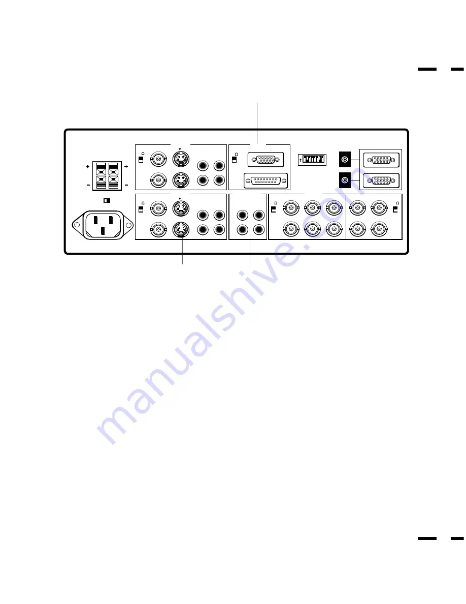
Terminal Board

DIP SW

REMOTE

EXT SPEAKERS

SPEAKERS MUST HAVE

MORE THAN 5WATT RATING

IMPEDANCE 8 OHM

AC IN

SPEAKER SELECT

RIGHT

LEFT

75

HIGH

INT

EXT

BNC

IN

OUT

IN

R

L(MONO)

AUDIO

THROUGHPUT

VIDEO 1

OUT

S

1  2  3  4  5  6  7  8

ON

75

HIGH

RGB1

PC / EXT CTL

75

HIGH

BNC

IN

OUT

IN

R

L(MONO)

AUDIO

VIDEO 2

OUT

S

IN

R

R

G

B

IN

OUT

H

V

L(MONO)

OUT

IN

OUT

75

HIGH

75

HIGH

RGB AUDIO

RGB 2

F

E

G

E

VIDEO 2

VIDEO 2 IN (BNC type) ....

Connect another VCR or laser disk player here to

display the video.

S-VIDEO 2 IN .....

Connect S-Video input from another external source like

a VCR.

THROUGH OUT (BNC type) .......

Connect to a second monitor’ s video input

to relay the video signal input at VIDEO 2 IN.

THROUGH OUT (S-VIDEO) .......

Connect to a second monitor’ s S-connector

input to relay the video signal input at S-VIDEO 2 IN.

75 

/HIGH Impedance Select Switch for BNC type ....

Set to “75 

” during

normal operation. In multiple connections using VIDEO 2 IN and

THROUGH OUT (BNC type) terminals, set to “HIGH” on all but the last

monitor. Set to “75 

” on the last monitor only.

AUDIO R IN .....

This is your right channel audio input for stereo sound.

AUDIO L IN (MONO) ......

This is your left channel audio input for stereo

sound coming from video equipment or audio system. It also serves as the

mono audio input.

AUDIO R THROUGH OUT .....

Connect to a second monitor’ s right channel

audio input.

AUDIO L THROUGH OUT .....

Connect to a second monitor’ s left channel

audio input.

Terminal Board(continued)

F

RGB 1 (MultiCable)

RGB Input/Throughput .....

Attach either end of the MultiCable to a computer,

and then attach the other end to either of these two connectors. You can then

use the remaining connector, if you wish, to output the computer signal to a

monitor. (If you do use a second monitor, turn the monitor switch to “on.”)

Either connector can be used for input or output, however they cannot both

be used for input simultaneously. It can damage your computer.

75 

/HIGH Impedance Select Switch ....

This switch should be “75

” for

normal use without external termination or when your RGB signal should be

terminated with 75

. Switch to the “HIGH” position when you have another

monitor attached to your RGB through-put connector.

G

RGB AUDIO

AUDIO R IN ....

This is where you connect RGB right audio output from a

computer or another RGB source.

AUDIO L IN(MONO) ...

This is where you connect RGB left audio output from

a computer or another RGB source.

AUDIO R THROUGH OUT ......

Connect to a second monitor’ s RGB right audio

input.

AUDIO L THROUGH OUT .....

Connect to a second monitor’s RGB left audio

input.

Содержание MultiSync XM29 Plus

Страница 1: ...ies Inc 1250 N Arlington Heights Road Suite 500 Itasca Illinois 60143 1248 R 29 Plus 29 Plus Printed in Japan 78408132 MultiSync is a registered trademark of NEC Technologies Inc in the U S A NEC is registered trademark of NEC Corporation 1993 by NEC Technologies Inc ...

Страница 2: ...ined below 40 C 2 Do not use the power cord polarized plug with extension cords or outlets unless the prongs can be completely inserted 3 Do not expose unit to rain or moisture 4 Avoid damage to the power cord and do not attempt to modify the power cord 5 Unplug unit during electrical storms or if unit will not be used over a long period 6 Do not open the cabinet which has potentially dangerous hi...

Страница 3: ...ne accumulation de chaleur interne Ne pas couvrir les trous d aération arrière ou installer l appareil dans un coffret fermé ou sur une étagère L appareil est équipé d ailettes de refroidissement sur le dessus Si l appareil est logé dans un coffret ou sur une étagère s assurer qu il y a un espace libre suffisant pour la dissipation de la chaleur Si l appareil est posé sur un coffret ou une étagère...

Страница 4: ...s of initial technical adjustments set up including adjustment of user controls These costs are the responsibility of the NECTECH dealer from whom the product was purchased 3 Payment of shipping charges HOW YOU CAN GET WARRANTY SERVICE 1 To obtain service on your product consult the dealer from whom you purchased the product or ship it prepaid to any authorized NECTECH service center 2 Whenever wa...

Страница 5: ...neral Controls Degaussing 27 Using OSM Controls 28 Direct Control Screen 29 Accessing OSM 32 CONTENTS OSM Menus 32 Visual Controls Group 32 H position H width Pin cushion Controls Group 33 V position V height V linearity Controls Group 33 Keystone Tilt Rotation Scan Select Controls Group 34 RGB Controls Group 35 OSM Location OSM Turn Off Time Control 36 Source Information 36 Volume Control 37 Rese...

Страница 6: ...binets A sleek sophisticated cabinet design complements your presentation environment and enhances the professionalism of your presentations Microsoft Plug and Play compatibility The only monitors in their class to include this standard that automatically optimizes display settings Supports most IBM VGA S VGA XGA Macintosh or any other RGB signals within a horizontal frequency range or 15 75 to 95...

Страница 7: ... SUB 15 pin type When you are in the OSM mode this button works as the minus button 6 VIDEO 2 Press to select an NTSC PAL SECAM or M NTSC compatible video source that is connected to the VIDEO 2 input terminal BNC type or S VIDEO 2 IN When you are in the OSM mode this button works as the up button NOTE S VIDEO IN terminals will take preference over VIDEO IN terminals when the video source is conne...

Страница 8: ...VIDEO 1 VIDEO 1 IN BNC type Connect a VCR or laser disk player here to display the video S VIDEO 1 IN Here is where you connect S Video input from an external source like a VCR THROUGH OUT BNC type Connect to a second monitor s video input to relay the video signal input at VIDEO 1 IN THROUGH OUT S VIDEO Connect to a second monitor s S connector input to relay the video signal input at S VIDEO 1 I...

Страница 9: ...or stereo sound coming from video equipment or audio system It also serves as the mono audio input AUDIO R THROUGH OUT Connect to a second monitor s right channel audio input AUDIO L THROUGH OUT Connect to a second monitor s left channel audio input Terminal Board continued F RGB 1 MultiCable RGB Input Throughput Attach either end of the MultiCable to a computer and then attach the other end to ei...

Страница 10: ...details J REMOTE IN OUT Connect the optional remote cable to the REMOTE IN terminal The REMOTE OUT terminal is used to connect several monitors together and allows all of the monitors to be controlled by one remote control NOTE Up to 50 monitors can be connected in the serial connection K PC EXT CTL IN D Sub 15 pin This terminal is used when power ON OFF input selection AUDIO MUTE PICTURE MUTE and...

Страница 11: ...rce from a computer connected to the RGB 1 IN terminal RGB 2 Press to select an RGB video source from a computer NEC scan converter or document camera connected to the RGB 2 IN terminal 79644641 POWER ON RGB 2 RGB 1 VIDEO 2 VIDEO 1 POSITION CONTROL PROCEED EXIT SCAN NORMAL SIDE PIN HEIGHT WIDTH BRIGHT CONTRAST MUTE NORMAL VOLUME OFF DEGAUSS MULTIMEDIA MONITOR RD 346E 3 4 OSM Control 4 POSITION CON...

Страница 12: ... PIN HEIGHT WIDTH BRIGHT CONTRAST MUTE NORMAL VOLUME OFF DEGAUSS MULTIMEDIA MONITOR RD 346E Visual Control B BRIGHT Adjusts the overall image and screen brightness Press and hold for a brighter picture Press and hold for a darker picture C CONTRAST Adjusts the image brightness in relation to the background Press and hold for higher contrast Press and hold for lower contrast NOTE The VISUAL CONTROL...

Страница 13: ...e remote sensor of the monitor The monitor will not function if there are objects between the remote control and the sensor or if strong light falls on the sensor Weak batteries will also prevent the remote control from properly operating the monitor 3 Close the battery compartment cover 1 Turn the remote control unit upside down Press down on the battery compartment grip and slide the compartment...

Страница 14: ...ee page 43 for pin assignments If you have some monitors you do not want to control by remote set to OFF Pin No 7 REMOTE ON OFF When this switch is set to ON SHORT the monitor can be controlled by the wireless remote control unit Pin No 8 OSM System Control Menu ON OFF When this switch is set to ON SHORT the system control menu is displayed In this menu the following features are enabled Power on ...

Страница 15: ...ut however they cannot both be used for input simultaneously It can damage your computer Document camera VCR Video copy stand or Multimedia application IBM XGA SuperVGA VGA or Compatibles Installation Wiring Diagram To D SUB 15 Pin input To R G B H V inputs BNC To EXTERNAL CONTROL D SUB 15 Pin input XP29Plus XM29Plus NEC IDC SERIES SCAN CONVERTER XP29 Plus XM29 Plus Macintosh or Compatibles IBM MA...

Страница 16: ...tion or configuring your monitor s image and monitor may require Connecting Your VCR or Laser Disc Player Using a common RCA cable and RCA audio cables not provided to connect your VCR or laser disc player to your MultiSync XP29 Plus XM29 Plus moni tor To make these connections simply 1 Turn off the power to your monitor and VCR or laser disc player 2 Connect one end of your RCA video cable to the...

Страница 17: ...TE OUT of the monitor to the REMOTE IN of the next monitor using the optional remote cable When using the RGB inputs THROUGH OUT Connections 1 RGB1 Connect D Sub 15 pin THROUGH OUT to an RGB input connector of other monitors RGB2 Connect the R G B H and V THROUGH OUT terminals to relay the signal input at the R G B H and V IN terminals 2 Set all the 75Ω HIGH impedance select switches on all but th...

Страница 18: ...T Do not connect speakers to both the monitor EXTERNAL SPEAKERS terminals and to the stereo amplifier This could damage both the monitor and the speakers VIDEO or RGB AUDIO L and R outputs of XP29Plus XM29Plus CAUTION Unplug the monitor and all connected components before con necting external speakers Use only speakers with 8 ohm impedance and a power output rating of 5 watts or more To connect ex...

Страница 19: ...ich may require demagnetizing to clear the problem Also if powered on for extended periods of time magnetic fields can be produced by the CRT itself causing color impurities In these cases use the DEGAUSS key once to demagnetize the picture tube Pressing this key once demagnetizes the picture tube for 5 seconds CAUTION Please allow a minimum of 30 minutes to elapse between uses of the DEGAUSS key ...

Страница 20: ...Control Screen You can adjust the raster visual and sound using the direct key on the remote control To switch to another control screen press any one of the other keys To end the OSM display press EXIT If no key operation is made within 3 seconds the OSM display will disappear a POSITION CONTROL Press to move the image right Press to move the image left Press to move the image up Press to move th...

Страница 21: ...iew of the selection of controls available Visual Controls Group The visual controls allow you to adjust the picture controls such as brightness contrast color tint and sharpness BRIGHTNESS Pressing or increases or decreases the image brightness level CONTRAST Pressing or increases or decreases the image contrast level SHARPNESS Pressing or increases or decreases the image sharpness level COLOR Pr...

Страница 22: ...N CUSHION Pressing or decreases or increases the curvature of the sides either inward or outward PIN BALANCE Pressing or decreases or increases the curvature of the sides to right or to left PIN CORNER Pressing or decreases or increases the curvature of the four corners inward outward NOTE The V LINEARITY controls allow you to adjust the spacing of the areas on the screen The object of this contro...

Страница 23: ...u you can select how long the monitor waits after the last touch of a key to shut off the OSM menu The preset choices are 5 10 30 and 120 seconds Note that 30 seconds is the factory preset OSM H POSI Pressing or moves the OSM menu right or left OSM V POSI Pressing or moves menu up or down OSM TURN OFF TIME Pressing or selects the preset time in increasing or decreasing order Source Information Sou...

Страница 24: ...e above warning statement will appear to confirm that you do want to reset individual settings NOTE In addition to OSM controls adjustments can be directly accessed with the remote control keys When adjusting with the remote control keys the on screen display for the related adjustment appears instead of the OSM menu When OSM ON OFF is set at OFF in the System Control menu see below OSM controls a...

Страница 25: ...on as follows POSITION CONTROL up down highlights one of the control items in the System control menus POSITION CONTROL proceeds to the selected menu choice POSITION CONTROL exits the current control and returns to its original System control menus EXIT exits the OSM controls POWER ON MODE This control allows you to set the monitor to default to any one of its inputs each time the monitor is turne...

Страница 26: ...ol The OSM control is available when ON is selected When the OSM does not appear the visual and raster controls are available with the remote control PC CONTROL This control allows you to activate the PC control function For more information see the following pages ...

Страница 27: ...nd No Connection Request to Send Ground Input Select Input Select Power ON OFF No Connection Degauss ON OFF Signal Ground EXT CTL EXT CTL EXT CTL EXT CTL External Control Pin No VIDEO1 VIDEO2 RGB1 RGB2 POWER OFF POWER ON DEGAUSS OFF DEGAUSS ON 4 OPEN GND OPEN GND 5 OPEN OPEN GND GND 10 OPEN GND 14 OPEN GND NOTE If EXT CTL is set to ON only EXT CTL will be effective for the above functions If EXT C...

Страница 28: ...quipment such as personal computer using the PC EXT CTL terminals The following sections explain the interface Interface Condition RS 232C Baud rate 9600 bps Data length 8 bits Parity Odd parity Stop bit 1 bit Communications mode Full duplex Command 1 Code based on the command system UNIT ID Code allocated to each equipment Allocate 80H to the XP29 Plus XM29 Plus Command 2 Code allocated to the ma...

Страница 29: ...n Power Off Degauss Control Length 00 00 00 COM2 4E 4F A1 COM1 3F 7F Contents Power On ACK Power Off ACK Input Switching ACK Degauss Control ACK Length 00 00 00 01 COM2 4E 4F B0 A1 PC CONTROL COMMAND LIST FOR USE WITH THE XP29 Plus XM29 Plus PC XP29 Plus XM29 Plus COM1 DF UA 80 COM2 B0 Length 02 Data 1 00 Data 2 VIDEO1 01 VIDEO2 02 RGB1 03 RGB2 04 Sum 12 13 14 15 COM1 3F UA 80 COM2 B0 Length 00 Da...

Страница 30: ...f center at a distance of within 22ft Set Pin no 7 of DIP SW to ON OPEN Set Pin no 6 of DIP SW to OFF SHORT Check the input signal Possible Cause Power cord unplugged Power outlet inactive Power of external equipment is not ON External equipment has been incorrectly connected Incorrect input selection Improper control setting Local interference Cable interconnections Input impedance is not correct...

Страница 31: ...XM29Plus 15 7 31 KHz to 65 KHz Automatically Vertical 40 Hz to 120 Hz Automatically Picture tube 27 inch Visual size 29 inch CRT size Diagonal Type A68 108 degree deflection Stripe trio pitch Ph 0 60 mm at center Ph 0 78 mm at corner Pv 0 56 mm Invar mask Medium short persistence phosphor Anti static electricity coating Optical filter coating Dynamic focus RGB Input Terminals RGB 1 D SUB 15pin min...

Страница 32: ... 2 7µsec Vertical 0 4 msec Current Rating AC 100 120 V 220 240 V 50 60 Hz Power Consumption XP29 Plus XP 2990 3 5 A maximum XM29 Plus XM 2960 3 5A maximum Dimensions 645 W x 533 H x 518 D mm 25 4 W X21 H X20 4 D inches Weight 53 5 kg 118 0 lbs Environmental Considerations Operating Temperature 0 to 40 Humidity 0 to 90 Altitude 0 to 10 000 feet Storage Temperature 10 to 50 Humidity 0 to 95 Altitude...

Страница 33: ...Multisync PROCEED VIDEO 1 EXIT VIDEO 2 RGB 1 RGB 2 POWER STANDBY 21 0 533mm 20 4 518mm 14 94 379 5mm 25 4 645mm 23 27 591mm Dimensions 20 4 518mm 56 55 ...

Страница 34: ...nce Chart Separate Sync Timing Charts VIDEO A B C D E O P Q R S VIDEO Sync Polarity Positive Negative HORIZONTAL VERTICAL Composite Sync A B C D E VIDEO O P Q R S VIDEO Sync Polarity Positive Negative HORIZONTAL VERTICAL 58 ...

Страница 35: ...hen at 15KHz Horizontal blanking should exceed 15 75 10µsec 31KHz fH 66KHz 3 6 µsec 66KHz fH 2 7 µsec Vertical Duty should be 0 2 to 10 Vertical sync width should exceed 40 µsec or 2 horizontal lines Vertical sync width plus back porch should exceed 0 4 msec Interlaced signals are not recommended Interlaced signals with composite sync may not be displayed A B C D E VIDEO O P Q R S P VIDEO Sync Pol...

Страница 36: ...ntal Pulse Width C Horizontal Back Porch D Horizontal Active Area E Horizontal Front Porch 640 480 37 860KHz 26 413µsec 1 270µsec 4 063µsec 20 317µsec 0 762µsec VESA 640 480 at 72Hz VESA 800 600 at 56Hz 800 600 35 156KHz 28 444µsec 2 000µsec 3 556µsec 22 222µsec 0 667µsec 1024 768 48 363KHz 20 677µsec 2 092µsec 2 462µsec 15 754µsec 0 369µsec VESA 1024 768 at 60Hz 1024 768 35 587KHz 28 100µsec 3 91...

Страница 37: ...79msec 0 106msec 0 607msec 15 840msec 0 026msec VESA 800 600 at 60Hz Resolution Vertical Frequency O Vertical Period P Vertical Pulse Width Q Vertical Back Porch R Vertical Active Area S Vertical Front Porch 640 350 70 080Hz 14 268msec 0 064msec 1 716msec 11 504msec 0 985msec 720 400 70 080Hz 14 268msec 0 064msec 0 890msec 13 156msec 0 159msec 720 350 87 850Hz 11 383msec 0 051msec 1 496msec 8 873m...

Страница 38: ... 4KHz 60Hz VESA 800x600 46 9KHz 75Hz REUTER 800x600 48 1KHz 72Hz H 98 1120x750 50 0KHz 60 1Hz MAC 832x624 49 7KHz 75Hz VESA 1024x768 56 5KHz 70Hz VESA 1024x768 60 0KHz 75Hz MAC 1024x768 60 2KHz 75Hz VESA 1280x1024 64 6KHz 60Hz VESA 1024x768 68 7kHz 85Hz MAC 1152x870 68 7KHz 75Hz VESA 1600x1200 75kHz 60Hz VESA 1280x1024 80 0KHz 75Hz VESA 1600x1200 87 5kHz 70Hz VESA 1600x1200 93 8KHz 75Hz NEG POS PO...

Страница 39: ...he phone number listed below For technical support or any questions concerning the operation of this product To arrange for on site repair service during the warranty period or after its expiration For the location of your nearest authorized NEC service center To report a DOA product and verify its status for return authorization 1 800 836 0655 Due to the size and weight of large screen presentati...

Страница 40: ......

Отзывы: