background image

English

English−25

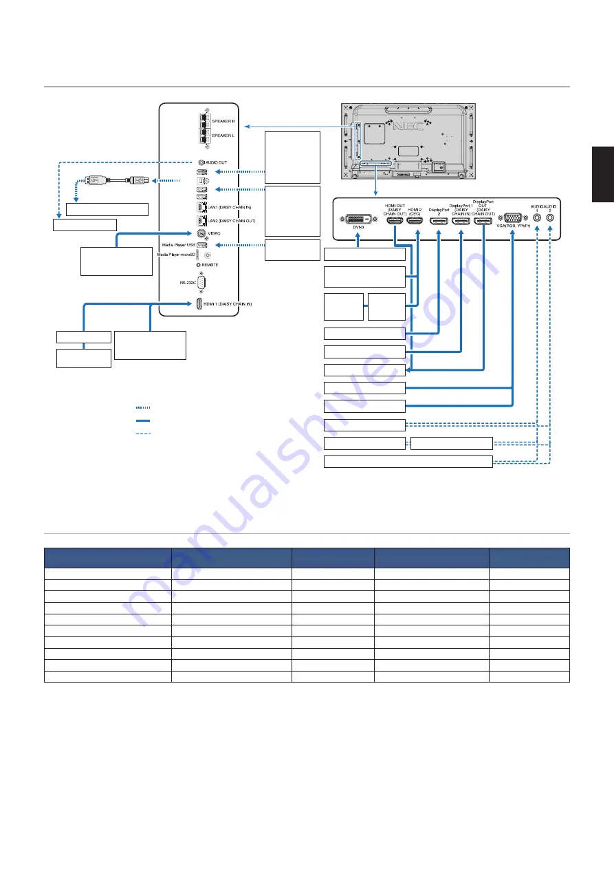
Wiring Diagram

USB1 (SENSOR)

USB2

USB CM1 (2A)

USB CM2

AUDIO

1

Dotted lines = other signal

Solid lines = video signal

Dashed lines = audio signal

VCR Player or 

DVD Player (Video)

Stereo Amplifier

USB port 

(Type-A)

USB devices 

such as a 

USB camera,  

USB storage  

device or USB  

color sensor

Devices that 

require power 

supply: 

Ex: Multi 

Presenter stick

USB storage  

device

USB port 

(Type-B)

USB cable

Computer (USB)*

1

AV Amplifier

Blu-ray or DVD 

Player (HDMI)

HDMI video player or 

Computer (HDMI)

Computer (Digital)

HDMI video player or 

Computer (HDMI)

Blu-ray or 

DVD Player 

(HDMI)

AV 

Amplifier

Computer (DisplayPort)

Computer (DisplayPort)

Second monitor*

Computer (Analog)

Computer

DVD Player (component)

DVD Player

Stereo Amplifier

VCR player or DVD player

*:  Multiple monitors that are daisy-chained have a limit to the number of connectible monitors. See 

page 71

.

*

1

:  The device connected to USB2 can control the device connected to USB1 (SENSOR). See the 

“Connecting a USB Device” on page 31

.

Connections

Connecting terminal

Setting in 

TERMINAL SETTINGS

Input signal name

Connecting audio terminal

Input button in remote 

control

DVI (DVI-D)

DVI MODE: DVI-PC/DVI-HD

DVI

IN1/IN2

DVI

HDMI1 (DAISY CHAIN IN)

VIDEO LEVEL: RAW/EXPAND*

2

HDMI1

HDMI1

HDMI1

HDMI2 (CEC)

VIDEO LEVEL: RAW/EXPAND*

2

HDMI2

HDMI2

HDMI2

DisplayPort 1 (DAISY CHAIN IN)

VIDEO LEVEL: RAW/EXPAND*

2

DisplayPort 1

DisplayPort 1

DisplayPort 1

DisplayPort 2

VIDEO LEVEL: RAW/EXPAND*

2

DisplayPort 2

DisplayPort 2

DisplayPort 2

VGA (RGB, YPbPr)

VGA MODE: RGB/YPbPr

VGA: RGB/YPbPr

IN1/IN2

VGA (RGB/YPbPr)

VIDEO

VIDEO

IN1/IN2

VIDEO

Option Board Slot (SLOT2)

VIDEO LEVEL: RAW/EXPAND*

2

OPTION

OPTION (ANALOG/DIGITAL)*

2

OPTION

Media Player USB/microSD

MP

Media Player USB/microSD

MEDIA PLAYER

Raspberry Pi Compute Module slot

VIDEO LEVEL: RAW/EXPAND*

2

COMPUTE MODULE

COMPUTE MODULE

COMPUTE MODULE

*

2

:  Please set appropriate setting for input signal.

Содержание MultiSync UN462A

Страница 1: ...ultiSync UN462VA MultiSync UN492S MultiSync UN492VS MultiSync UN552A MultiSync UN552S MultiSync UN552VS MODEL UN462A UN462VA UN492S UN492VS UN552A UN552S UN552VS The model name and serial number can be found in the rating label on the rear side of monitor ...

Страница 2: ...ing Mounting Accessories 14 Using a Wall Mount Adapter 14 Installing and Removing the Optional Table Top Stand 15 Installing an Option Board 16 Installing an Optional Sensor Unit 17 Chapter 2 Parts Name and Functions Control Panel 19 Terminal Panel 20 Wireless Remote Control Optional 22 Chapter 3 Connections Wiring Diagram 25 Connections 25 External Video Connections 26 Connecting to a Personal Co...

Страница 3: ...Picture In Picture matrix 57 Setting Security and Locking the Monitor Controls 59 Password Security 59 Locking the Button Controls 60 Media Player Settings 63 Network Other Settings 64 Copying Files to the microSD memory card 65 Using Emergency Contents 69 Chapter 6 Multi Monitor Setup Connecting Multiple Monitors 71 Video Out Connection 73 Setting the Remote Control ID Function 74 Chapter 7 Exter...

Страница 4: ...nal Resources Appendix B OSD Controls List INPUT 107 PICTURE 107 AUDIO 112 SCHEDULE 112 MULTI INPUT 114 OSD 117 MULTI DISPLAY 118 DISPLAY PROTECTION 122 CONTROL 123 OPTION 128 SYSTEM 128 COMPUTE MODULE 129 Appendix C Manufacturer s Recycling and Energy Information Disposing of your old NEC product 131 Energy Saving 131 ...

Страница 5: ...rt 15 of FCC Rules Operation is subject to the following two conditions 1 This device may not cause harmful interference and 2 this device must accept any interference received including interference that may cause undesired operation U S Responsible Party NEC Display Solutions of America Inc Address 3250 Lacey Rd Ste 500 Downers Grove IL 60515 Tel No 630 467 3000 Type of Product Display Monitor E...

Страница 6: ...with the table below If a power cord is not supplied with this equipment please contact NEC For all other cases please use the power cord with the plug style that matches the power socket where the monitor is located The compatible power cord corresponds to the AC voltage of the power outlet and has been approved by and complies with the safety standards in the country of purchase This equipment i...

Страница 7: ...monitor so that heat can properly dissipate Do not block ventilated openings or place the monitor near a radiator or other heat source Do not put anything on top of the monitor Handle with care when transporting Save packaging for transporting When running the cooling fan continuously we recommend wiping clean the ventilation holes a minimum of once a month To ensure the monitor s reliability plea...

Страница 8: ...a lint free non abrasive cloth Avoid using any cleaning solution or glass cleaner Please do not rub the LCD panel with a hard or abrasive material Please do not apply pressure to the LCD panel surface Please do not use OA cleaner as it will cause deterioration or discoloration on the LCD panel surface Cleaning the Cabinet Unplug the power supply Gently wipe the cabinet with a soft cloth To clean t...

Страница 9: ...tiProfiler supported Multiple color modes can be easily configured and selected using the MultiProfiler software which can be downloaded from our website Uniformity see page 111 Provides a more consistent luminance and color across the screen by compensating for variations in luminance and color that are inherent to LCD panels Stand alone calibration see page 51 This function updates the monitor s...

Страница 10: ...ovided in the box This device cannot be used or installed without the Tabletop Stand or other mounting accessory for support For proper installation it is strongly recommended to use a trained NEC authorized service person Failure to follow NEC standard mounting procedures could result in damage to the equipment or injury to the user or installer Product warranty does not cover damage caused by im...

Страница 11: ... fan to ON within the FAN CONTROL menu within the OSD see page 122 NOTE To avoid scratching the LCD panel always place a soft cloth such as a blanket that is larger than the monitor s screen area on the table before laying the monitor face down 2 Install the remote control Optional batteries The remote control is powered by two 1 5 V AAA batteries To install or replace batteries 1 Press and slide ...

Страница 12: ...vision reception For DVI USB and mini D Sub 15 pin please use a shielded signal cable with ferrite core For HDMI DisplayPort and D Sub 9 pin please use a shielded signal cable Use of other cables and adapters may cause interference with radio and television reception 6 Turn on the power for the external equipment and the monitor When connected to a computer switch on the monitor power first 7 Oper...

Страница 13: ...llation re modeling or natural disasters Failure to comply with these recommendations could result in voiding the warranty To ensure safe installation use two or more brackets to mount the unit Mount the unit to at least two points on the installation location Please note the following when mounting on wall or ceiling CAUTION When using mounting accessories other than those that are NEC approved t...

Страница 14: ...ul for alignment Pin e g Pin installation in multi monitor configuration PIN 8 2 m m Pin instruction You can fix each monitor position with pins When you use pins please refer to the instructions below 1 Connect all vertical position monitors using pins 2 Connect each vertical monitor using pins For UN552S UN552VS Please locate the spacer at the edge of rear side monitor Attach it by using the dou...

Страница 15: ... monitor from falling off from the wall or ceiling NEC strongly recommends using a safety wire Prepare the monitor using mounting accessories such as hook eyebolt or mounting parts and then secure the monitor with a safety wire The safety wire must not be tight Please make sure the mounting accessories are strong enough to support the monitor before mounting it Installing a wire to a monitor with ...

Страница 16: ...ve at least 4 inches 100 mm of space between the monitor and the wall for proper ventilation NOTE Allow for adequate ventilation or provide air conditioning around the monitor so that heat can properly dissipate away from the monitor and from the mounting equipment Orientation When using the monitor in the portrait position it should be rotated clockwise so that the left side is moved to the top r...

Страница 17: ...uipment especially when you use monitors in a multiple screen configuration Mounting on ceilings CAUTION Ensure that the ceiling is strong enough to support the weight of the unit and the mounting equipment over time against earthquakes unexpected vibrations and other external forces Be sure the unit is mounted to a solid structure within the ceiling such as a support beam Secure the monitor using...

Страница 18: ...mage the monitor When using mounting accessories other than NEC compliant and approved they must comply with the VESA Flat Display Mounting Interface Standard FDMI NOTE Prior to installation place the monitor face down on a flat even surface that is larger than the monitor screen Use a sturdy table that can easily support the weight of the monitor 1 UN552A UN552S UN552VS WM 55UN L or WM 55UN P UN4...

Страница 19: ...UN492S UN492VS DO NOT use this monitor on the floor with the table top stand Please use this monitor on a table or with a mounting accessory for support Soft cloth Optional table top stand Table Prevent Tipping CAUTION When using the monitor with the optional table top stand fasten the monitor to a wall using a cord or chain that can support the weight of the monitor in order to prevent the monito...

Страница 20: ...igure 3 Figure 1 Figure 2 Figure 3 Figure 4 4 Insert the Option Board into the monitor and fix it in place with the removed screws Figure 4 Recommended Fasten Force 139 189 N cm NOTE Unless your monitor is purchased as part of a special bundle package no Option Boards will be in the box or installed in the monitor These are optional accessories available for separate purchase Please contact your s...

Страница 21: ...ons below to avoid damage to the monitor For the UN462A UN462VA UN552A When installing the sensor unit on the upper side of the monitor do not use the screw If the sensor unit is installed using a screw it could damage the monitor For the UN492S UN492VS Please use the M3 x 6 screw attached to the monitor It isn t possible to use a screw of the Optional Sensor Unit For fixing the sensor unit within...

Страница 22: ...English 18 Chapter 2 Parts Name and Functions This Chapter Includes Control Panel on page 19 Terminal Panel on page 20 Wireless Remote Control Optional on page 22 ...

Страница 23: ... the left when navigating through the OSD menu options Acts as minus button to decrease the adjustment of an OSD menu option after it has been selected with the INPUT SET button F r Button up button Activates the OSD menu when the OSD menu is turned off Acts as up button to move the highlighted area up to select adjustment items within the OSD menu G s Button down button Activates the OSD menu whe...

Страница 24: ...nal from DisplayPort 1 or OPTION F DisplayPort IN DisplayPort1 DAISY CHAIN IN DisplayPort2 DisplayPort signals input G HDMI IN HDMI1 DAISY CHAIN IN HDMI2 CEC HDMI signals input H HDMI OUT HDMI OUT DAISY CHAIN OUT Output signal from HDMI 1 DVI IN or OPTION I DVI IN DVI D Digital RGB signals input from a computer or HDTV device having a digital RGB output See page 116 NOTE This connector does not su...

Страница 25: ...8 Ω speaker R Option Board Slot Slot for installation of a Slot 2 type Option Board See page 16 NOTE Please contact your supplier for a list of compatible Option Boards S Security Slot Security and theft protection lock slot compatible with Kensington security cables equipment NOTE For products visit Kensington s website T Rating Label Intelligent wireless data sensor Sensor for wireless communica...

Страница 26: ...ress and hold the DISPLAY button for more than 5 seconds to unlock the remote See page 61 G MENU Button Opens and closes the OSD menu See page 38 H AUTO SET UP Button Enters auto setup menu See page 109 I EXIT Button Acts as a back button within the OSD to move to the previous OSD menu Acts as an EXIT button to close the OSD when on the main menu J Button up down button Acts as navigation buttons ...

Страница 27: ...for NONE SUPER in INPUT CHANGE TILE MATRIX CLOSED CAPTION is not available when STILL is active If the input signal is option this button s action depends on which Option Board is installed in the monitor IMAGE FLIP Button Toggle switches between H FLIP V FLIP 180 ROTATE and NONE See page 111 ACTIVE PICTURE Button Selects the active picture when Multi Picture Mode is enabled See page 55 MULTI PICT...

Страница 28: ... external equipment s power as this may result in loss of image Do not use an attenuating built in resistor audio cable Using an audio cable with a built in resistor will lower the sound level Before making connections Turn off the device s power before connecting it to the monitor Refer to the device s user manual for available connection types and instructions for the device We recommend turning...

Страница 29: ...nitors See page 71 1 The device connected to USB2 can control the device connected to USB1 SENSOR See the Connecting a USB Device on page 31 Connections Connecting terminal Setting in TERMINAL SETTINGS Input signal name Connecting audio terminal Input button in remote control DVI DVI D DVI MODE DVI PC DVI HD DVI IN1 IN2 DVI HDMI1 DAISY CHAIN IN VIDEO LEVEL RAW EXPAND 2 HDMI1 HDMI1 HDMI1 HDMI2 CEC ...

Страница 30: ...tical MODE1 MODE2 1 1a 1 2 640 x 480 31 5 kHz 60 Hz Yes Yes Yes Yes Yes Yes 800 x 600 37 9 kHz 60 Hz Yes Yes Yes Yes Yes Yes 1024 x 768 48 4 kHz 60 Hz Yes Yes Yes Yes Yes Yes 1280 x 720 45 0 kHz 60 Hz Yes Yes Yes Yes Yes Yes 1280 x 768 47 8 kHz 60 Hz Yes Yes Yes Yes Yes Yes 1280 x 800 49 7 kHz 60 Hz Yes Yes Yes Yes Yes Yes 1280 x 960 60 0 kHz 60 Hz Yes Yes No No No No 1280 x 1024 64 kHz 60 Hz Yes ...

Страница 31: ...on When removing this cable hold down the top button to release the lock To output DisplayPort audio set DisplayPort1 or DisplayPort2 at AUDIO INPUT in the OSD or choose DisplayPort1 or DisplayPort2 by the remote control AUDIO INPUT button To display individual images at each connected monitors with the DisplayPort OUT connector please set DisplayPort1 2 and MST at DisplayPort in the TERMINAL SETT...

Страница 32: ...o be configured using the monitor s web controls The function names and location in the web controls are the same as the OSD menu Enabling CEC 1 Connect a CEC device to the HDMI2 port Press the HDMI2 button on the remote control 2 Press the MENU button to open the OSD 3 Navigate to CONTROL then to CEC 4 Select ON for CEC then YES for the AUTO TURN OFF and AUDIO RECEIVER 5 Select YES under SEARCH D...

Страница 33: ...roSD with CPRM is not supported microSD UHS 1 or UHS 2 are not supported When inserting a microSD memory card please make sure of the microSD memory card is in the correct direction then insert it Fully insert the microSD memory card and press in until the spring lock is engaged When ejecting a microSD memory card from the microSD card slot press the center of the microSD memory card to release th...

Страница 34: ...n Board or a Raspberry Pi Compute Module Interface Board and Raspberry Pi Compute Module are installed in the monitor it will show as available in the list in the INPUT of the OSD menu Option Boards the Raspberry Pi Compute Module Interface Board and Raspberry Pi Compute Module are available separately and must be physically installed in the monitor This document contains instructions for how to u...

Страница 35: ...nformation See page 96 Functions as a standard USB port when used with the Raspberry Pi Compute Module Interface Board and Raspberry Pi Compute Module See page 104 USB CM2 Service port Please do not connect devices Functions as a standard USB port when used with the Raspberry Pi Compute Module Interface Board and Raspberry Pi Compute Module See page 104 Media Player USB USB downstream port Type A ...

Страница 36: ...Range for the Optional Remote Control on page 34 Using Power Management on page 34 Showing the Information OSD on page 35 Switching Between Picture Modes on page 35 Setting the Aspect Ratio on page 36 Using Point Zoom on page 37 OSD On Screen Display Controls on page 38 Using the Media Player on page 40 ...

Страница 37: ...to MST Glowing amber No AV signal input has been detected by the monitor during the period of time you set with network signal input Blinking amber No AV signal input has been detected by the monitor during the period of time you set no network signal input Glowing red Turn off the monitor by the remote control or the monitor button Turn on the monitor by the remote control or the monitor button 1...

Страница 38: ... approved DPM Display Power Management function This function decreases the power consumption of the monitor when it is not in use When connected to a computer power consumption by the monitor reduces automatically if the keyboard or mouse are not used during the time set in the computer s power management settings Refer to your computer s user manual for more information When connected to an AV s...

Страница 39: ...me B Audio input name C Picture aspect D Input Signal Information E Multi Picture information F Communication Info H Switching Between Picture Modes Press the PICTURE MODE button on the wireless remote control to cycle through the SpectraView Engine picture modes from 1 to 5 The picture modes are pre configured with settings for general use See Advanced Color Adjustment on page 48 for instructions...

Страница 40: ...LL WIDE DYNAMIC 1 1 ZOOM NORMAL Aspect ratio of image Unchanged view 2 Recommended selection for picture aspect 2 Description 4 3 NORMAL Reproduces the aspect ratio that is sent from the source DYNAMIC Expands a 4 3 picture to fill the entire screen with non linearity Some of the outside image area will be cut off due to expansion Squeeze FULL Fills the entire screen Letterbox WIDE Expands a 16 9 ...

Страница 41: ...k distorted when using this function POINT ZOOM is not available when the OSD settings are enabled for IMAGE FLIP except for NONE MULTI PICTURE MODE SCREEN SAVER SUPER in INPUT CHANGE CLOSED CAPTION TILE MATRIX and TEXT TICKER When the ASPECT setting is DYNAMIC or ZOOM pressing the POINT ZOOM button automatically sets the ASPECT to FULL and then starts the POINT ZOOM function After exiting POINT Z...

Страница 42: ...d m2 GAMMA Custom CUSTOMVALUE 2 2 WHITE 10000K x 0 279 y 0 292 RED x 0 642 y 0 332 GREEN x 0 307 y 0 602 BLUE x 0 153 y 0 053 Input source Main Menu Icons Main Menu Item Sub Menu Key Guide Adjustment Settings This menu is only available when the optional Raspberry Pi Compute Module Interface Board and Raspberry Pi Compute Module are installed Remote Control Press or to navigate to a sub menu Press...

Страница 43: ...ettings OSD Select options related to the on screen display menu such as language the amount of time the OSD stays on screen the location of the menu transparency rotation etc MULTI DISPLAY Set the monitor s monitor ID configure settings for multi monitor setup PROTECT Select options related to protecting the monitor hardware such as configuring the cooling fans adjusting automatic power save and ...

Страница 44: ...e file list for a connected USB storage device This is a color icon when a USB storage device is connected and the file system can be read If this icon is gray the Media Player does not detect or it is not able to read a USB storage device NOTE If Media Player contents are played while TILE MATRIX is active the image play timing may have a time delay between monitors If the monitor is used in port...

Страница 45: ... creation or size file capacity The default sorting order is by Name EJECT Unmount the USB storage device or the microSD memory card Please select EJECT when the file list is displayed ENT Button remote control Select or deselect individual items such as files to include in the SLIDESHOW or a folder to use for AUTO PLAY and PRESET CONTENTS NOTE A maximum of 300 items can be displayed in a folder i...

Страница 46: ...e previous video file or image file in the current folder Starts the video or slideshow from the selected file Resumes the video or slideshow after pause Resumes the video from rewind or fast forward Skips to the next video file or image file in the current folder Stops the video or slideshow Pauses the video or slideshow Reverses through a video file until the Play Pause or Stop button is pressed...

Страница 47: ...T POINT ZOOM button to select BGM If BGM does not have a check mark next to it the audio file you selected will not play To choose what should happen when the slideshow is not set to REPEAT press the down arrow to PLAY END SCREEN then press SET POINT ZOOM button Highlight the option you want and press SET POINT ZOOM button BLACK SCREEN when the last file is played a black screen is shown until the...

Страница 48: ...mote control 7 Navigate to OK and press SET POINT ZOOM button to save the changes and return to the MEDIA PLAYER home screen Auto play automatically plays any pictures or videos in the selected folder The images and videos will be displayed in the sorted order When AUTO PLAY is enabled the monitor will start auto play as follows When powering on the monitor with a USB storage device or microSD mem...

Страница 49: ...mp3 MP3 Additional Information Item Conditions Resolution JPEG Up to 5000 x 5000 PNG Up to 4000 x 4000 MPEG1 480 30fps MPEG2 MP ML MP HL 1080p 30fps 1080i 60fps H 264 High profile Lv 4 2 1080p 30fps 1080i 60fps WMV Advanced L3 Simple Main Video bit date Up to 15 Mbps Audio sampling rate Up to 48 kHz Audio bit rate MP2 Up to 384 Kbps MP3 Up to 320 Kbps AAC Up to 1440 Kbps NOTE Some files may not pl...

Страница 50: ... Operation This Chapter Includes Creating a Power Schedule on page 47 Advanced Color Adjustment on page 48 Multi Picture Mode on page 55 Setting Security and Locking the Monitor Controls on page 59 Media Player Settings on page 63 ...

Страница 51: ...ess the SET POINT ZOOM button If the schedule is to be run every day choose EVERY DAY and press the SET POINT ZOOM button If a weekly schedule is desired choose the days of the week using the and buttons and pressing SET POINT ZOOM button to select Then highlight the EVERY WEEK option and press SET POINT ZOOM button Please set WEEKDAY WEEKEND or HOLIDAY in the same manner NOTE The WEEKDAY WEEKEND ...

Страница 52: ...or management features and the user color controls allow a unique level of precision to be achieved The white point is adjusted using a CIE x y control and the grayscale response of the display is calculated and managed by the monitor itself The SVE includes Uniformity Correction where different levels of compensation can be selected to enable a trade off between the most uniform brightness and co...

Страница 53: ... sRGB The standard color setting of the Internet Windows operating systems and many smart phone and other digital cameras Recommended setting for general color management AdobeRGB Wider color gamut setting used in high end graphics applications such as professional digital still cameras and printing eciRGB_v2 Color setting recommended by Europe printing group ECI The European Color Initiative DCI ...

Страница 54: ...range A larger value will improve white saturation but the picture become darker When Auto is selected Luminance is used as the peak luminance setting DICOM DICOM GSDF Grayscale Standard Display Function is typically used for medical imaging Programmable A programmable gamma curve can be loaded using optional NEC software Custom Set a custom value for Peak luminance CUSTOM VALUE The gamma value is...

Страница 55: ...olor sensor This sensor connects directly to the USB1 SENSOR port on the monitor The monitor automatically takes screen measurements directly from the color sensor See Appendix A for purchase and availability information Or A near range colorimeter with a measurement readout display in CIE Y x y format with Y in units of cd m2 Measurements are taken manually and each reading must be entered into t...

Страница 56: ...ues individually entered via the OSD using the remote control Y is in units of cd m2 Depending on the monitor usage and other factors performing a Self Calibration at least once per year is recommended Reset calibration This deletes the color measurement data created by the Self Calibration function and returns to the original factory internal reference color measurement data All Picture Modes wil...

Страница 57: ...t the monitor that will be used as the Target or source of the copy operation A This function will measure the luminance and white point of the target monitor A and set these values to the current Picture Mode of the destination monitor B You can also fine tune the measurement result while checking the screen color If you want to return to the measured value select re measurement The Self Calibrat...

Страница 58: ...isplayPort1 DisplayPort2 OPTION 1 VGA RGB HDMI1 HDMI2 COMPUTE MODULE 2 STANDARD sRGB CINEMA CUSTOM1 CUSTOM2 HIGHBRIGHT 1 This function depends on which Option Board is installed in the monitor 2 This input is available when the optional Raspberry Pi Compute Module Interface Board and Raspberry Pi Compute Module are installed See page 104 For VGA YPbPr VIDEO MP STANDARD CINEMA CUSTOM1 CUSTOM2 HIGHB...

Страница 59: ... select this option to have a second input viewed in a subset window PBP Picture By Picture select this option to have the two inputs viewed next to each other PIP Picture In Picture settings 1 Navigate to INPUT SELECT on the OSD Select an input source for Picture1 main input and Picture2 secondary input 2 Navigate to ACTIVE PICTURE on the OSD Change the Active Picture to PICTURE2 The Picture Size...

Страница 60: ... source Adjusting the size of the Text Ticker area adjusts how much of the top or left portion of the second source is displayed Detect automatically turns the Text Ticker function on and off based on the presence of the secondary video signal Input Select the input signal for the primary PICTURE1 and secondary PICTURE2 sources Input Detect select one of the functions to enable automatic detection...

Страница 61: ... No Yes Yes Yes Yes Yes VIDEO VIDEO Yes Yes No No Yes Yes Yes Yes Yes No No OPTION Option Board Slot SLOT2 DP No Yes Yes Yes Yes Yes Yes Yes Yes Yes Yes Option Board Slot SLOT2 HDMI Yes Yes No No Yes Yes Yes No Yes Yes No MP Yes Yes No No Yes Yes Yes No Yes No Yes DisplayPort 1 1a HDMI MODE2 Sub picture Main picture DisplayPort1 DisplayPort2 DVI HDMI1 HDMI2 VGA RGB VGA YPbPr Video OPTION MP Connec...

Страница 62: ...o No No No No Option Board Slot SLOT2 HDMI No No No No Yes Yes Yes No No No No MP No No No No Yes Yes Yes No No No Yes DisplayPort 1 2 HDMI MODE2 Sub picture Main picture DisplayPort1 DisplayPort2 DVI HDMI1 HDMI2 VGA RGB VGA YPbPr Video OPTION MP Connector DisplayPort1 DAISY CHAIN IN DisplayPort2 DVI D HDMI1 DAISY CHAIN IN HDMI2 CEC VGA RGB YPbPr VIDEO Option Board Slot SLOT2 DP Option Board Slot ...

Страница 63: ...tions in the monitor s OSD menu These settings can also be configured using the monitor s web controls The function names and location in the web controls are the same as the OSD menu See page 84 The menu options for Security and Lock Settings are in the CONTROL menu in both the OSD menu and web controls MULTI INPUT OPTION C MODULE CONTROL NETWORKINFORMATION LAN CHANGEPASSWORD SECURITY IRLOCKSETTI...

Страница 64: ...the PASSWORD field to access the SECURE MODE settings 3 Select the type of SECURE MODE you want to use OFF no password is required START UP LOCK the password is required when turning on the monitor from the main power switch When this option is selected the password is only required on power cycle using the main power switch or after power failure This option does not prompt for a password when us...

Страница 65: ... unlocked POWER select UNLOCK to be able to use the button when the IR Remote is locked Select LOCK to lock the button VOLUME select UNLOCK to be able to control the volume with the VOL VOL buttons when the IR Remote is locked Select LOCK to prevent volume adjustment When activating the volume lock the display volume will immediately change to the MIN VOL value MIN VOL and MAX VOL the volume butto...

Страница 66: ...d or unlocked POWER select UNLOCK to be able to use the button when the keys are locked VOLUME select UNLOCK to be able to control the volume with the and buttons when the keys are locked Select LOCK to prevent volume adjustment When activating the volume lock the display volume will immediately change to the MIN VOL value MIN VOL and MAX VOL the and volume keys are unlocked and the volume can onl...

Страница 67: ...M Check the check box to enable BGM PLAY END SCREEN Selects a setting for when the slideshow finishes Black screen When the slideshow finishes a black screen is displayed File list When the slideshow finishes it goes back to the file list screen Save last screen When the slideshow finishes the last slideshow image is kept on the screen Auto Play Automatically plays any pictures or videos in the selecte...

Страница 68: ...IP address for the monitor If you want to manually assign an IP address for the monitor you will need to assign one to the Media Player as well Otherwise the IP address will be automatically assigned to the Media Player and possible conflicts on the network may occur IP ADDRESS SUBNET MASK DEFAULT GATEWAY DNS DNS PRIMARY DNS SECONDARY NETWORK INFORMATION shows the current network settings for the ...

Страница 69: ... Player basically tells the monitor that there is no current video signal and to shift to no signal mode This allows the monitor to register No Signal and enter power save mode just as it would on the other video inputs when loss of video signal occurs The amount of time between when the Media Player is last used before it tells the monitor to shift to no signal can be adjusted The monitor shifts ...

Страница 70: ... turn off the monitor s main power Ejecting the microSD memory card or turning off the monitor while copying files may corrupt the data If you press the STANDBY button on the remote control or the button on the monitor while the LED indicator is blinking red the monitor goes to standby after completing the copy function NOTE If the connection to a shared folder fails an error message is shown and a...

Страница 71: ...ress the Choose File button 7 Navigate to the where the files you want to add to the card are located Select the file you want to copy to the microSD memory card then press Open 8 Press OK to confirm the file upload 9 The file will now copy to the microSD memory card If you selected a file type that the Media Player cannot read a message will show on the file upload screen that the file cannot be ...

Страница 72: ...lect files and folders Pressing DELETE opens the DELETE FOLDERS FILES window Pressing OK deletes the selected files or folders 3 CREATE Create opens a window to name and add a new folder to the microSD memory card Input folder name and select OK A maximum of 255 alphanumeric characters is allowed 4 RELOAD Refreshes the microSD memory card data in the web browser 5 THUMB LIST Switches between displ...

Страница 73: ...TO SD CARD VIEWER window 3 Press the SEARCH button to display the IP ADDRESS of the currently connected monitor and all compatible monitors on the same network 4 Select the IP address under the IP ADDRESS MP column to access the Media Player s web controls for the monitor you want to copy files to To open the other monitor s web page in a new tab right click on its IP address To open the other mon...

Страница 74: ...English 70 Chapter 6 Multi Monitor Setup This Chapter Includes Connecting Multiple Monitors on page 71 Video Out Connection on page 73 Setting the Remote Control ID Function on page 74 ...

Страница 75: ...OTE AUTO ID will be automatically executed When you use this function it is recommended that monitors be chained by DisplayPort cable This function is released if MOTION in SCREEN SAVER is activated Example of installation via LAN H MONITORS 3 V MONITORS 3 Master monitor SETTING COPY copies some of the OSD menu categories to other monitors in the video wall when chained together TILE MATRIX allows...

Страница 76: ...if fast moving content is displayed Applying the FRAME COMP is needed for a specific installation AUTO Sets total delay value each delay value is set automatically by setting of H MONITORS V MONITORS and POSITION in TILE MATRIX MANUAL Sets delay value to every monitors V SCAN REVERSE Reverse scanning image direction to create a smooth motion image ORIGINAL FRAME COMP V SCAN REVERSE V SCAN Directio...

Страница 77: ...monitor to output a signal from DisplayPort Out This monitor s signal output function supports contents protected by HDCP HDCP content can be distributed across up to 3 connected monitors When using an Option Board please set SLOT2 CH SETTING to CH1 then set SLOT2 CH SELECT to DisplayPort See page 128 NOTE Please use slot2 type option boards which outputs DisplayPort signal For HDMI Out Select eit...

Страница 78: ...trolled via remote The remote can then be used to operate the monitor having that specific Monitor ID number When 0 is selected or when the remote control is in normal mode all monitors will be operated To Set Reset Remote Control Mode ID Mode To enter ID Mode press the REMOTE ID SET button and hold down for 2 seconds Normal Mode To return to Normal Mode press the REMOTE ID CLEAR button and hold d...

Страница 79: ... the REMOTE ID SET button while using the keypad to input the REMOTE CONTROL ID number 1 100 The REMOTE ID NUMBER should match the MONITOR ID number of the monitor to be controlled 3 Point the remote control towards the remote sensor of the desired monitor and press the REMOTE ID SET button The MONITOR ID number is shown in red on the monitor If the REMOTE CONTROL ID is 0 then all monitors in rang...

Страница 80: ... device There are two options to connect an external device to control the monitor NEC Display Wall Calibrator or NaViSet Administrator allows you to control the monitor settings and get the monitor status including calibration information RS 232C terminal Connecting an external device to the RS 232C terminal of the monitor with a RS 232C cable LAN port Connecting a network to the LAN1 DAISY CHAIN...

Страница 81: ...1 30 41 30 43 02 43 32 30 33 44 36 30 30 30 31 03 73 0d Power OFF 01 30 41 30 41 30 43 02 43 32 30 33 44 36 30 30 30 34 03 76 0d Input Source Select DisplayPort1 01 30 41 30 45 30 41 02 30 30 36 30 30 30 30 46 03 04 0d or 01 30 41 30 45 30 41 02 31 31 30 36 30 30 30 46 03 04 0d Input Source Select DisplayPort2 01 30 41 30 45 30 41 02 30 30 36 30 30 30 31 30 03 73 0d or 01 30 41 30 45 30 41 02 31 3...

Страница 82: ...and which is listed in the External_Control pdf See page 104 but also supports common ASCII control command which is used for controlling the NEC monitor or projector from a connected PC For further information please visit our website Parameter Input command Status command Input signal name Response Parameter Response Error status DVI dvi dvi or dvi1 error temp Temperature abnormal HDMI1 hdmi1 hd...

Страница 83: ...changed to the same language which is selected for the monitor For the Change Language function it is necessary that the connected HDMI CEC supported device be able to cope with multi language AUTO TURN OFF System Standby If the monitor is set to standby using the optional wireless remote control HDMI CEC supported devices also go into standby at the same time If the monitor goes into standby whil...

Страница 84: ...may not work RS 232C Cable Computer RS 232C NOTE If your computer is equipped only with a 25 pin serial port connector a 25 pin serial port adapter is required Contact your supplier for details For the pin assignment please see 2 RS 232C input output on page 81 To control the monitor via commands sent from a computer connected with an RS 232C cable please use the control command Instructions for t...

Страница 85: ...olling the Monitor via LAN Connecting to a Network Using a LAN cable allows you to specify the Network Settings and the Alert Mail Settings by using an HTTP server function To use a LAN connection you are required to assign an IP address The monitor will obtain an IP address automatically when connected to a DHCP network Example of LAN connection Server Hub NOTE Use a category 5 or higher LAN cabl...

Страница 86: ...ase execute AUTO ID IP to automatically assign unique IDs to each monitor see page 120 before trying to control a monitor by manually specifying the ID number Master Monitor Sub Monitors Connector Connector IN OUT IN OUT RS 232C LAN2 DAISY CHAIN OUT LAN1 DAISY CHAIN IN LAN2 DAISY CHAIN OUT REMOTE LAN1 DAISY CHAIN IN Connection LAN Cable Next monitor LAN Cable LAN1 LAN2 LAN1 LAN2 LAN2 ...

Страница 87: ...istrator The monitor may not respond if the buttons shown on the browser are repeatedly pressed in rapid intervals Should this happen wait a moment and repeat If you still can t get a response turn the monitor off and then back on Preparation Before Use Connect the monitor to the network using a commercially available LAN cable before attempting to use browser operations Operation with a browser t...

Страница 88: ...inks on the left side of the monitor web controls to configure the settings available in the monitor s OSD Please see page 106 for the full list of OSD menu controls INPUT PICTURE AUDIO SCHEDULE MULTI INPUT OSD MULTI DISPLAY DISPLAY PROTECTION CONTROL OPTION SYSTEM COMPUTE MODULE NOTE The buttons in the monitor web controls function as follows APPLY Saves the settings CANCEL Returns to the previou...

Страница 89: ... when MANUAL is selected for IP SETTING NOTE Set as 0 0 0 0 to delete the setting DNS Set for IP ADDRESS setting of DNS server AUTO The DNS server connected to the monitor will automatically assign its IP address MANUAL Manually enter the IP address of the DNS server that is connected with the monitor PRIMARY DNS Enter the primary DNS server settings of the network connected with the monitor NOTE ...

Страница 90: ...n is required for the email transmission Up to 60 alphanumeric characters can be used Password This sets the password for logging into the authentication server when authentication is required for the email transmission Up to 60 alphanumeric characters can be used Test Mail Click on this button to send a test email to check if your settings are correct NOTE If an alert email isn t received when pe...

Страница 91: ...ion Error code Temperature Temperature abnormal 0xA0 0xA1 0xA2 Fan Cooling fan abnormal 0x80 0x81 Power Power abnormal 0x70 0x71 0x72 0x78 Inverter Backlight Inverter or backlight abnormal 0x90 0x91 No Signal No signal 0xB0 PROOF OF PLAY Lower the log storage 0xD0 System Error System error 0xE0 AMX Settings Click on AMX on the left column below HOME AMX BEACON To turn on or off for the detection f...

Страница 92: ... characters can be used HOST NAME MP Type in the hostname of the network to be used in the Media Player connected to the monitor Up to 15 alphanumeric characters can be used Domain Name Type in the domain name of the network which is connected with the monitor Up to 60 alphanumeric characters can be used Network Service Settings Click on NETWORK SERVICE on the left column below HOME PJLink CLASS S...

Страница 93: ...ters long MEMO PASSWORD The default is 0000 MEMO PASSWORD ENABLE A MEMO PASSWORD is required when selecting MEMO PASSWORD ENABLE SD CARD VIEWER setting Click SD CARD VIEWER on the left side of HOME Please refer to Using SHARED SD card SETTINGS See page 64 Intelligent Wireless Data This function can be used to get the monitor status via wireless communication even when the main power off Some of th...

Страница 94: ...UDIO OUT Normal Audio or No Audio TIME year month day hour minutes second EXPANSION DATA 00h Normal Proof of Play event 01h Proof of Play event is last power on time 10h MEDIA PLAYER is stop 11h MEDIA PLAYER is start 12h MEDIA PLAYER is pause 13h MEDIA PLAYER error occur 20h Contents Copy from USB 21h Contents Copy form network folder 30h Contents Copy Success 31h Contents Copy Error No media 32h ...

Страница 95: ...English English 91 Chapter 8 Troubleshooting This Chapter Includes Screen Image and Video Signal Issues on page 92 Hardware Issues on page 93 Image Persistence on page 95 ...

Страница 96: ...o the decision intention of the HDCP community Digital Content Protection LLC Snowy Picture Black Screen in DVI input Check the DVI MODE setting when a DVD player or computer equipment is connected to the DVI input Image persistence Please be aware that LCD Technology may experience a phenomenon known as Image Persistence Image Persistence occurs when a residual or ghost image of a previous image ...

Страница 97: ...s in the shadows and highlights and the image appears overly high in contrast Blacks are dark grey and whites are dull change the VIDEO LEVEL to EXPAND Dulling blacks and whites can occur when the VIDEO LEVEL is set to RAW while the source video signal s color levels are RGB Limited RGB 16 235 which effectively appears to prevent the monitor from obtaining its full brightness range and the image a...

Страница 98: ...ULE SETTINGS Media player function does not recognize the USB storage device Check that a USB storage device is connected to the Media Player USB port Check the file format of the USB storage device if it is not recognized by the monitor MicroSD memory card does not work Check that the microSD memory card is properly connected Check the microSD memory card format LED Indicator Patterns LED on the ...

Страница 99: ...ence For long life use as a Public Display Image Sticking of LCD Panel When an LCD panel is operated continuously for long hours a trace of electric charge remains near the electrode inside the LCD and a residual or ghost image of the previous image may be observed Image Persistence Image Persistence is not permanent but when a fixed image is displayed for long period ionic impurities inside the L...

Страница 100: ...VIDER LICENSED TO PROVIDE AVC VIDEO NO LICENSE IS GRANTED OR SHALL BE IMPLIED FOR ANY OTHER USE ADDITIONAL INFORMATION MAY BE OBTAINED FROM MPEG LA L L C SEE HTTP WWW MPEGLA COM 2 MPEG 4 Visual THIS PRODUCT IS LICENSED UNDER THE MPEG 4 VISUAL PATENT PORTFOLIO LICENSE FOR THE PERSONAL AND NON COMMERCIAL USE OF A CONSUMER FOR i ENCODING VIDEO IN COMPLIANCE WITH THE MPEG 4 VISUAL STANDARD MPEG 4 VIDE...

Страница 101: ...DMI Connector Digital RGB HDMI HDCP 1 4 2 2 AUDIO AUDIO Input Stereo Mini Jack Analog Audio Stereo L R 0 5 Vrms HDMI Connector Digital Audio PCM 32 44 1 48 kHz 16 20 24 bit DisplayPort Connector Digital Audio PCM 32 44 1 48 kHz 16 20 24 bit AUDIO Output Stereo Mini Jack Analog Audio Stereo L R 0 5 Vrms Speaker Output External Speaker Jack 15 W 15 W 8 ohm Control RS 232C In LAN Remote IN D Sub 9 pi...

Страница 102: ... Connector Digital RGB HDMI HDCP 1 4 2 2 AUDIO AUDIO Input Stereo Mini Jack Analog Audio Stereo L R 0 5 Vrms HDMI Connector Digital Audio PCM 32 44 1 48 kHz 16 20 24 bit DisplayPort Connector Digital Audio PCM 32 44 1 48 kHz 16 20 24 bit AUDIO Output Stereo Mini Jack Analog Audio Stereo L R 0 5 Vrms Speaker Output External Speaker Jack 15 W 15 W 8 ohm Control RS 232C In LAN Remote IN D Sub 9 pin R...

Страница 103: ...ector Digital RGB HDMI HDCP 1 4 2 2 AUDIO AUDIO Input Stereo Mini Jack Analog Audio Stereo L R 0 5 Vrms HDMI Connector Digital Audio PCM 32 44 1 48 kHz 16 20 24 bit DisplayPort Connector Digital Audio PCM 32 44 1 48 kHz 16 20 24 bit AUDIO Output Stereo Mini Jack Analog Audio Stereo L R 0 5 Vrms Speaker Output External Speaker Jack 15 W 15 W 8 ohm Control RS 232C In LAN Remote IN D Sub 9 pin RJ 45 ...

Страница 104: ...or Digital RGB HDMI HDCP 1 4 2 2 AUDIO AUDIO Input Stereo Mini Jack Analog Audio Stereo L R 0 5 Vrms HDMI Connector Digital Audio PCM 32 44 1 48 kHz 16 20 24 bit DisplayPort Connector Digital Audio PCM 32 44 1 48 kHz 16 20 24 bit AUDIO Output Stereo Mini Jack Analog Audio Stereo L R 0 5 Vrms Speaker Output External Speaker Jack 15 W 15 W 8 ohm Control RS 232C In LAN Remote IN D Sub 9 pin RJ 45 10 ...

Страница 105: ...r Digital RGB DisplayPort V1 2 HDCP 1 3 HDMI HDMI Connector Digital RGB HDMI HDCP 1 4 2 2 AUDIO AUDIO Input Stereo Mini Jack Analog Audio Stereo L R 0 5 Vrms HDMI Connector Digital Audio PCM 32 44 1 48 kHz 16 20 24 bit DisplayPort Connector Digital Audio PCM 32 44 1 48 kHz 16 20 24 bit AUDIO Output Stereo Mini Jack Analog Audio Stereo L R 0 5 Vrms Speaker Output External Speaker Jack 15 W 15 W 8 o...

Страница 106: ...r Digital RGB HDMI HDCP 1 4 2 2 AUDIO AUDIO Input Stereo Mini Jack Analog Audio Stereo L R 0 5 Vrms HDMI Connector Digital Audio PCM 32 44 1 48 kHz 16 20 24 bit DisplayPort Connector Digital Audio PCM 32 44 1 48 kHz 16 20 24 bit AUDIO Output Stereo Mini Jack Analog Audio Stereo L R 0 5 Vrms Speaker Output External Speaker Jack 15 W 15 W 8 ohm Control RS 232C In LAN Remote IN D Sub 9 pin RJ 45 10 B...

Страница 107: ...nector Digital RGB HDMI HDCP 1 4 2 2 AUDIO AUDIO Input Stereo Mini Jack Analog Audio Stereo L R 0 5 Vrms HDMI Connector Digital Audio PCM 32 44 1 48 kHz 16 20 24 bit DisplayPort Connector Digital Audio PCM 32 44 1 48 kHz 16 20 24 bit AUDIO Output Stereo Mini Jack Analog Audio Stereo L R 0 5 Vrms Speaker Output External Speaker Jack 15 W 15 W 8 ohm Control RS 232C In LAN Remote IN D Sub 9 pin RJ 45...

Страница 108: ...psulates this communications protocol into a Python library for rapid development https github com NECDisplaySolutions necpdsdk Projector Monitor Common ASCII Control Command Reference Manual PDF document This document defines the communications protocol for externally controlling the basic functions of the display via LAN using a simple English like syntax It is suitable for easy integration into...

Страница 109: ...soft Windows and macOS is available for purchase and may require the use of a supported external color sensor Please contact an authorized NEC dealer or see the NEC Display Solutions website in your region for purchase information and availability NaViSet Administrator software This free software is an advanced and powerful network based control monitoring and asset management system for NEC displ...

Страница 110: ...PICTURE on page 107 AUDIO on page 112 SCHEDULE on page 112 MULTI INPUT on page 114 OSD on page 117 MULTI DISPLAY on page 118 DISPLAY PROTECTION on page 122 CONTROL on page 123 OPTION on page 128 SYSTEM on page 128 COMPUTE MODULE on page 129 Default values can be provided on request ...

Страница 111: ...e is used with supporting software 3D LUTs are uploaded to the monitor via application software ON Enables Activates the 3D LUT function for the selected picture mode OFF Disables Deactivates the 3D LUT function for the selected picture mode Compare In this mode colors that lie outside the boundaries of the 3D LUT are shown in gray It is useful for determining out of gamut colors COLOR VISION EMU ...

Страница 112: ...ber produces a better effect but may also affect power consumption and lifetime of the monitor BRIGHTNESS 2 BACKLIGHT Adjusts the overall image and background brightness Press or to adjust NOTE When MODE1 or MODE2 is selected in ROOM LIGHT SENSING this function cannot be changed BRIGHTNESS 3 Adjusts the image brightness in relationship to the background Press or to adjust GAMMA 2 3 Select a monito...

Страница 113: ... when new timing is detected H POSITION VGA RGB VGA YPbPr inputs only Controls the horizontal position of the image within the display area of the LCD Press button to move right Press button to move left V POSITION VGA RGB VGA YPbPr inputs only Controls the vertical position of the image within the display area of the LCD Press button to move up Press button to move down CLOCK VGA RGB input only P...

Страница 114: ... Fills the entire screen WIDE Expands a 16 9 letterbox signal to fill the entire screen DYNAMIC Expands 4 3 pictures to fill the entire screen with non linearity image Part of the outside image area will be cut off due to expansion 1 1 Shows the image in a 1 by 1 Pixel format If the input resolution is higher than the recommended resolution the image will be scaled down to fit the screen ZOOM Expa...

Страница 115: ...tarts When an IMAGE FLIP option is selected except for NONE the following functions are disabled MULTI PICTURE MODE TEXT TICKER STILL POINT ZOOM and TILE MATRIX When the input signal is interlaced the image may be distorted NONE Normal mode H FLIP Flips the image left right V FLIP Flips the image up down 180 ROTATE Rotates the image 180 degrees OSD FLIP Determines the OSD menu direction If ON is s...

Страница 116: ...ys in the video that may occur due to video processing such as DEINTERLACE to be matched by an equal delay in the audio signal to avoid lip sync errors DELAY TIME RESET Resets all AUDIO options back to factory settings except for VOLUME 1 This function depends on which Option Board installed in the monitor SCHEDULE SCHEDULE MENU SCHEDULE SETTINGS Creates a working schedule for the monitor see page...

Страница 117: ...e same day yearly leave the field blank MONTH Press the or button to cycle through to the month you want to use for the holiday If the holiday repeats on the same day monthly leave the field blank DAY If the holiday is on a specific day in a month such as the 5th press SET to select DAY Press the to highlight the day field then press the or button to cycle through to the day you want to use for th...

Страница 118: ...t the month day and time for when Daylight Saving ends TIME DIFFERENCE Set the time difference for the real time clock adjustment When Daylight Saving starts this is the amount of time the real time clock will be adjusted OFF TIMER Powers off the monitor after the time period shown next to the slider Press the or button on the remote control to adjust the timer from 1 to 24 hours NOTE Schedules do...

Страница 119: ...e right and pressing the button moves it to the left Pressing the button moves the Active Picture up and pressing the button moves it down NOTE The Active Picture s position can be moved using the remote control without opening the OSD menu Press the ACTIVE PICTURE button on the remote control to select the picture to move Use the same buttons on the remote control to change the picture position N...

Страница 120: ...le in PRIORITY 3 except for a slot 2 type PC option If DisplayPort1 is set to PRIORITY 1 2 or 3 the OPTION slot 2 type PC option DP input cannot be chosen for any of the priority settings If OPTION slot 2 type PC option DP is set to PRIORITY 1 2 or 3 the DisplayPort1 input cannot be chosen for any of the priority settings INPUT CHANGE Sets the speed at which the monitor changes to a different vide...

Страница 121: ...ut and blackout of the image RAW For computer settings Show all input signals of 0 255 gray levels EXPAND For audio visual equipment settings Expands the input signals from 16 235 gray levels to 0 255 gray levels AUTO Automatically sets input signals by adjusting connected equipment NOTE This function is available only in HDMI or DisplayPort or OPTION and is selected at INPUT SIGNAL SIGNAL FORMAT ...

Страница 122: ...lays the MEMO title and message set via the HTTP server For more detail please refer to the MEMO Settings on page 89 INPUT NAME Renames the current input Custom names with a maximum of 14 characters including spaces can be set The characters can be a mix of letters A Z numbers 0 9 and some symbols CLOSED CAPTION VIDEO input only Activates closed captioning NOTE This function is disabled if any of ...

Страница 123: ... they function as FULL aspect when the tile matrix is active While the tile matrix is active changing the aspect setting to DYNAMIC or ZOOM or changing the zoom level does not affect the picture When the tile matrix deactivates any settings changed while the tile matrix was active are immediately applied POINT ZOOM function automatically deactivates when TILE MATRIX is activated Please refer to th...

Страница 124: ...of monitors to be targeted using a single command providing high speed parallel operation on daisy chained displays It is useful for scenarios such as rapid switching of video inputs or tile matrix configurations within a video wall The GROUP ID function is used only via LAN or RS 232C commands from your software or control system Monitors can be assigned to any of the 10 available Group IDs label...

Страница 125: ...ver a LAN such as 192 168 0 or 10 0 0 The fourth octet is set at BASE NUMBER and counts up by 1 starting from the master monitor NOTE BASE ADDRESS is only available when IP ADDRESS or ID and IP is selected for the SETTING ITEM ID IP SETTING START Highlight YES then press SET on the remote control to activate the automatic number function which first detects the number of monitors connected in the ...

Страница 126: ...al status of the fans backlight and temperature sensors SCREEN SAVER Use the SCREEN SAVER function to reduce the risk of Image Persistence NOTE When the screen saver starts the image aspect is changed to FULL When the screen saver stops the aspect will return to the current ASPECT setting The screen saver cannot be selected for signal input of 3840 x 2160 at 60 Hz When the MOTION option is set to ...

Страница 127: ...WER ON DELAY and INTELLI WIRELESS DATA CONTROL CONTROL MENU NETWORK INFORMATION Shows the current network settings LAN Configures the monitor s network settings either automatically or manually NOTE When changing the LAN settings it will take several seconds for the new LAN settings to be applied IP SETTING When AUTO is selected the IP address is automatically obtained from the DHCP server When MA...

Страница 128: ...AY button on the remote control and hold it down for more than 5 seconds MODE SELECT Selects the mode UNLOCK ALL LOCK or CUSTOM LOCK UNLOCK All buttons on the remote control are available for normal operation ALL LOCK Locks all remote control buttons CUSTOM LOCK All remote buttons are locked except for the following buttons which can be individually set to be locked or unlocked POWER Select UNLOCK...

Страница 129: ... be set to UNLOCK for this function INPUT Select UNLOCK and then select up to 3 input buttons to remain unlocked Select LOCK to lock all input buttons CHANNEL Select UNLOCK to be able to change channels with the CH ZOOM button when the IR remote is locked Select LOCK to lock these buttons ACTIVATE DEACTIVATE Select ACTIVATE to activate all settings To return to normal operation press and hold the ...

Страница 130: ... AUTO BRIGHTNESS and BACKLIGHT in SCREEN SAVER functions are disabled Do not select this function when AUTO BRIGHTNESS function is any setting other than OFF Do not cover the room light sensor when ROOM LIGHT SENSING is enabled ROOM LIGHT SENSING is enabled when it is set to MODE1 or MODE2 HUMAN SENSING 2 Automatically adjusts the backlight and volume levels based on whether or not a human presenc...

Страница 131: ...not be available as a selection USB POWER Select ON to supply power to the USB CM1 2A port NOTE Power consumption by devices connected to this port depends on the USB devices CEC Provides CEC Consumer Electronics Control compatible media players connected via HDMI the ability to communicate and allows limited control between the device and the monitor Only available for HDMI inputs CEC When ON is ...

Страница 132: ...shut down manually SLOT2 CH SETTING Selects signal type according to the slot 2 type option specifications AUTO Sets the signal type automatically CH1 Fills the screen entirely with the signal which is selected in SLOT2 CH SELECT CH2 The DisplayPort signal is displayed on the left half of the screen the TMDS signal is displayed on the right half If the internal PC does not support either one of th...

Страница 133: ...ear as a USB device to a PC connected to the USB2 input on the display and can be programmed with an Operating System When set to Disable the Compute Module will boot normally IR SIGNAL Enables or disables the forwarding of IR remote control signals MONITOR CONTROL Enables or disables the internal serial connection between the display and the Compute Module SHUTDOWN SIGNAL Enables or disables the ...

Страница 134: ...EC DISPLAY SOLUTIONS is strongly committed to environmental protection and sees recycling as one of the company s top priorities in trying to minimize the burden placed on the environment We are engaged in developing environmentally friendly products and always strive to help define and comply with the latest independent standards from agencies such as ISO International Organisation for Standardiz...

Страница 135: ...INPUT DETECT is set to a setting except for NONE USB POWER is set to ON DisplayPort in the TERMINAL SETTINGS is set to MST Power consumption Glowing amber 2 0 W or less with 1 port connection 3 0 W or less with all ports connection Time for power management function 10 sec Default setting Power consumption Blinking amber 0 5 W or less Time for power management function 3 min Default setting Except...

Отзывы: