background image

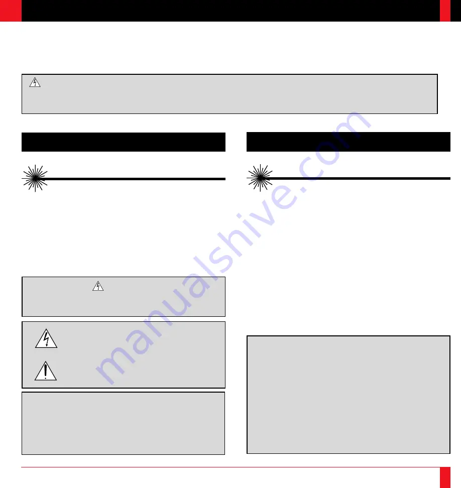
RF Interference

WARNING

The Federal Communications Commission does not allow any modifications or
changes to the unit EXCEPT those specified by NEC Technologies in this
manual. Failure to comply with this government regulation could void your
right to operate this equipment.

This equipment has been tested and found to comply with the limits for a Class
A digital device, pursuant to Part 15 of the FCC Rules. These limits are
designed to provide reasonable protection against harmful interference in a
commercial installation. This equipment generates, uses and can radiate radio
frequency energy and, if not installed and used in accordance with the instruc-
tions, may cause harmful interference to radio communications. Operation of
this equipment in a residential area is likely to cause harmful interference in
which case the user will be required to correct the interference at their own
expense.

DOC Compliance Notice

This Class A digital apparatus meets all requirements of the Canadian Interfer-
ence-Causing Equipment Regulations.

WARNING

TO PREVENT FIRE OR SHOCK, DO NOT EXPOSE THIS UNIT TO RAIN OR
MOISTURE. DO NOT USE THIS UNIT’S GROUNDED PLUG WITH AN
EXTENSION CORD OR IN AN OUTLET UNLESS ALL THREE PRONGS
CAN BE FULLY INSERTED. DO NOT OPEN THE CABINET. THERE ARE
HIGH-VOLTAGE COMPONENTS INSIDE. ALL SERVICING MUST BE

DONE BY QUALIFIED NEC SERVICE PERSONNEL.

2

Precautions

Please read this manual carefully before using your NEC MultiSync LT81/LT100 Projector and keep the manual handy for future reference.

Your serial number is located beneath the main power switch on the back of your MultiSync LT81/LT100.  Record it here:

CAUTION

To turn off main power, be sure to remove the plug from power outlet. The power outlet socket should be installed as near to the equipment as
possible, and should be easily accessible.

I M P O R T A N T   I N F O R M A T I O N

CAUTION

LASER RADIATION-
DO NOT STARE INTO BEAM

WAVE LENGTH: 670 nm
MAX. OUTPUT: 1 mW
CLASS II LASER PRODUCT

CAUTION

TO PREVENT SHOCK, DO NOT OPEN THE CABINET. NO USER-
SERVICEABLE PARTS INSIDE. REFER SERVICING TO QUALIFIED
NEC SERVICE PERSONNEL.

This symbol warns the user that uninsulated voltage within the
unit may be sufficient to cause electrical shock. Therefore, it is
dangerous to make any kind of contact with any part inside of
the unit.

This symbol alerts the user that important information concern-
ing the operation and maintenance of this unit has been pro-
vided. The information should be read carefully to avoid prob-
lems.

1

CAUTION

LASER RADIATION-
DO NOT STARE INTO BEAM

WAVE LENGTH: 645 nm (640-660 nm)
MAX. OUTPUT: 1 mW
CLASS II LASER PRODUCT

LT100 Remote Control

LT81 Remote Control

Содержание MultiSync LT81

Страница 1: ...2 Printed in Japan Ultra Portable Projector Ultra Portable Projector Projector User s Manual NEC Technologies Inc 1250 N Arlington Heights Road Suite 500 Itasca Illinois 60143 1248 MultiSync LT81 100 NEC Technologies ...

Страница 2: ...LLY INSERTED DO NOT OPEN THE CABINET THERE ARE HIGH VOLTAGE COMPONENTS INSIDE ALL SERVICING MUST BE DONE BY QUALIFIED NEC SERVICE PERSONNEL 2 Precautions Please read this manual carefully before using your NEC MultiSync LT81 LT100 Projector and keep the manual handy for future reference Your serial number is located beneath the main power switch on the back of your MultiSync LT81 LT100 Record it h...

Страница 3: ...l into your projector disconnect it immediately and have the object removed by a qualified NEC service person 3 Do not place any liquids on top of your projector Do not look into the lens while the projector is on Serious damage to your eyes could result Do not look into the laser pointer while it is on and do not point the laser beam at another person Serious injury could result 4 Important Safeg...

Страница 4: ...iel Brouilleur du Canada Importantes précautions de sécurité Les points suivants sont des précautions de sécurité importantes destinées à garantir une longue durée de service du projecteur et afin d éviter un incendie et des risques d électrocution S assurer de lire attentivement ces précautions de sécurité et respecter tous les avertissements décrits ci dessous Installation 1 Pour un fonctionneme...

Страница 5: ...lacement de la lampe Effectuer le remplacement de la lampe suivant les instructions de la page 85 Assurez vous de bien remplacer la lampe lorsque le voyant d usure s allume Si vous continuez d utiliser la lampe après 1000 heures d utilisation l ampoule peut se briser et des brisures de verre peuvent être éparpillées dans le compartiment de la lampe Ne les touchez pas car elles peuvent vous blesser...

Страница 6: ...l expenses for covered items But we will not pay for the following 1 Removal or installation charges L I M I T E D W A R R A N T Y 9 2 Costs of initial technical adjustments set up including adjustment of user controls These costs are the responsibility of the NECTECH dealer from whom the product was purchased 3 Payment of shipping charges HOW YOU CAN GET WARRANTY SERVICE 1 To obtain service on yo...

Страница 7: ...ingYour Document Camera 51 ConnectingYour VCR Or Laser Disc Player 52 Connecting An External Monitor 52 ConnectingYour Remote Mouse Receiver 53 T A B L E O F C O N T E N T S 11 3 Operation General Controls 57 Using The Menus 59 Menu Descriptions Functions 61 Source Menu Source Icons 61 Image Adjust Menu Sound And Picture Control Icons 63 Power Menu Projector Control Icons 67 Settings Menu Maintena...

Страница 8: ... The optional LT Viewer kit allows you to start your presentation even when a PC is not available at the site The image capture enables you to use the entire picture as a background image or to create slides optional LTViewer required 13 INTRODUCTION 14 An image can be projected from in front or behind a screen and the projector can even be installed on the ceiling NEC Technologies exclusive AccuB...

Страница 9: ...NTRODUCTION 16 Mouse adapter For Macintosh User s manual Signal cable 15 Pin Mini D Sub To 15 Pin Mini D Sub connector Power cable M u l t i S y n c U l t r a P o r t a b l e P r o j e c t o r Registration card Mouse adapter For IBM PS 2 Introductory Training CD ROM Serial cable Carrying case for LT100 Remote control case Q u i c k C o n n e c t G i d e Quick Connect Guide NEC MultiSync LT81 LT100...

Страница 10: ... Features M E M U S E L E C T E N T E R S T A T U S P O W E R O N O F F AC IN Remote Sensor Power Switch AC Input Connect the supplied power cable s three pin plug here Slot for Kensington MicroSaver Security System Rear Foot Adjustable on LT100 only Terminal Panel Carrying handle Zoom Ring Lever One Touch Tilt Button LT100 only Adjustable Foot Remote Sensor Remote Sensor Lever type Rear Foot LT81...

Страница 11: ...links for one minute then lights up and the projector goes on standby The projector will not accept operation instructions for the one minute during which the LED is blinking during switching on or off as described above 6 Status Indicator When this is lit red continually it s warning you that the projec tion lamp has exceed 1000 hours of service After this light ap pears it is advisable to replac...

Страница 12: ...reo sound 21 INTRODUCTION 22 PC CONTROL VIDEO INPUT RGB INPUT OUTPUT OUTPUT S VIDEO VIDEO L MONO R AUDIO OUTPUT INPUT RGB RGB AUDIO AUDIO REMOTE CONTROL S Video Input Here is where you connect S Video input from an external source like a VCR NOTE S Video provides more vivid color and higher resolution than the traditional composite video format 3 PC Control Port Use this port to connect your PC to...

Страница 13: ...an external monitor from the VIDEO audio input or RGB audio input source 6 Built in Security Slot This security slot supports the MicroSaver Security System MicroSaver is a registered trademark of Kensington Microware Inc The logo is trademarked and owned by Kensington Microware Inc 23 INTRODUCTION 24 PC CONTROL VIDEO INPUT RGB INPUT OUTPUT OUTPUT S VIDEO VIDEO L MONO R AUDIO OUTPUT INPUT RGB RGB ...

Страница 14: ...EO MENU LASER R CLICK RGB PC CARD S VIDEO ON POWER 4 5 6 7 8 9 10 1 3 2 5 Power On And Off If your main power switch is turned on you can use these buttons to turn your MultiSync LT81 LT100 Projector on and off 6 Video Button Press to select an NTSC PAL SECAM or NTSC4 43 compatible video source from a VCR DVD player laser disc player or document camera 7 S Video Button Press to select an S Video s...

Страница 15: ...ove the picture 16 Picture Mute Button This button turns off the image and sound for a short period of time Press again to restore the image and sound 16 15 13 14 11 12 INTRODUCTION 28 18 17 Magnify Button Use the or button to adjust the image size up to 400 18 Slide Button Press to advance the next file or slide and to return to the previous file or slide the optional LT Viewer board required 19 ...

Страница 16: ...ith the lens cap I N S T A L L A T I O N 2 29 SelectingA Location The further your projector is from the screen or wall the larger the image The minimum size the image can be is approximately 24 0 61 m measured diagonally when the projector is roughly 4 feet 1 2 m from the wall or screen The largest the image can be is 300 7 6 m when the projector is about 40 35 feet 12 3 m from the wall or screen...

Страница 17: ...44 162 180 610 914 1067 1219 1372 1524 1829 2286 2743 3048 3658 4115 4572 Tele For Screen Sizes of 24 to 300 inches not indicated on the projection tables use the formulas on the next page 40 60 70 80 90 100 120 150 180 200 240 270 300 11 4 11 4 11 4 11 4 11 3 11 3 11 3 11 3 11 3 11 3 11 2 11 2 32 48 56 64 72 80 96 120 144 160 192 216 813 1219 1422 1626 1829 2032 2438 3048 3658 4064 4877 5486 84 4...

Страница 18: ...f screen A C cosα B 3 7H C WIDE 2 0262H 2 437 225 4 C TELE C WIDE 21 3 D E 2 E H 423 A Distance between lens center and screen center B Vertical distance between lens center and screen bottom screen top for ceil ing mount C Horizontal throw distance between screen surface and projector lens D Vertical distance between screen center and screen bottom screen top for ceiling mount E Screen Height Scr...

Страница 19: ... on the front of the projector just above the feet to release the one touch tilt feet There is approximately 5 0 of up and down adjustment for the front of the projector 35 A Top view B Side view screen INSTALLATION 36 screen Up Down Focus ring Zoom ring lever Up Down LT81 To center the image vertically B raise the lever type foot on the rear straight up 6 To fine tune the image s position vertica...

Страница 20: ...ow LT81 MEMU SELEC T ENTER STATU S POWE R ON OFF Projector Zipper Note book PC Other Accessories When restoring the remote control place the case on the functional face to prevent possible malfunction 2 Unfold carrying case 3 Put the projector in the large compartment of the case 4 Zip up the sides of the case 5 Place notebook computer into carrying case 6 Store remote control and other accessorie...

Страница 21: ... your notebook computer into the front pouch 6 Latch the belt 7 Store the remote control and other accessories in the side pouches on the carrying case 2 1 When storing the remote control place the remote in its protective case The case will keep the remote buttons from being acci dentally pushed while it is being stored or trans ported This will keep the batteries from being dis charged 4 Zip up ...

Страница 22: ...rself NOTE Distances may vary 5 41 If your projector is mounted on the ceiling and your image is upside down use the Menu and Select buttons on your projector cabinet or buttons on your remote control to correct the orientation See page 70 INSTALLATION 42 233 303 200 261 100 131 80 104 60 78 40 53 24 31 1 2m 3 94ft 2 1m 6 89ft 3 15m 10 33t 4 2m 13 78ft 5 3m 17 39ft 10 65m 34 94ft 12 3m 40 35ft 15 ...

Страница 23: ...jector Remote Mouse Receiver Remote Control Guideline 1 Plug the serial cable with the remote mouse receiver into your computer s mouse port and restart your computer to gain remote mouse control 2 When using the remote control s built in infrared mouse on a laptop computer the laptop s mouse trackball or trackpad will be disabled Disconnect the infrared receiver and restart your computer to regai...

Страница 24: ...or 45 INSTALLATION 46 When using a Macintosh with the LT81 LT100 set the DIP switch of the supplied pin adapter according to your resolution After setting restart your Macintosh See the following pages for setting of the DIP switch When using with a Macintosh SVGA 8002600 XGA 10242768 is recommended if your Macintosh supports this mode When using with a Macintosh PowerBook output may not be set to...

Страница 25: ...ns set the DIP switch to the 13 fixed mode and then restart your Macintosh After that restore to a displayable mode and then restart the Macintosh again Make sure that LT81 LT100 and your Macintosh are connected with the pin adapter and the supplied signal cable mini D Sub 15 pin connector and then restart your Macintosh NOTE Refer to your computer s owner s manual for more information about your ...

Страница 26: ...e that Windows is about to resize your display When asked if you want to keep your settings select Yes Method 2 1 Click on your My Computer icon 2 Open Control Panel and select Display 3 Change your resolution and click OK after the new resolution is selected 4 You may be asked to reboot for the changes to take effect or you ll get a message that Windows is about to resize your display When asked ...

Страница 27: ...amera s video output requirements 51 INSTALLATION 52 Connecting Your VCR Or Laser Disc Player Use common RCA cables not provided to connect your VCR or laser disc player to your MultiSync LT81 LT100 Projector To make these connections simply 1 Turn off the power to your projector and VCR or laser disc player 2 Connect one end of your RCA cable to the video output connector on the back of your VCR ...

Страница 28: ...ial cable from the remote mouse receiver to your PC s mouse port Use the 6 pin adapter for connecting to a PS 2 computer For Macintosh Remove your current mouse from your computer attach the Macintosh adapter to the remote mouse receiver s serial cable and connect the receiver to your mouse port 3 When the remote mouse receiver is installed it will disable your regular mouse disconnect the remote ...

Страница 29: ... Mouse Receiver LT100 only m You can daisy chain as many as five projectors and operate them with the same remote control LT100 only To do so 1 Turn off your computer 2 Use the remote control cables supplied to connect the Remote Control Output of one projector to the Remote Control Input of the next until all the projectors are connected RGB INPUT S VIDEO OUTPUT INPUT RGB REMOTE CONTROL Insert th...

Страница 30: ...ard button on the remote control to display the image Or press the Menu button on the cabinet and use the icons to select your video source Video S Video RGB or PC Card O P E R A T I O N 3 57 3 Adjust The Image SizeAdjust the size of the screen with the zoom ring lever on the projector 4 Focus Adjust the focus with the focus ring on the projector 5 Turning Off The Projector First press the off but...

Страница 31: ... change is stored until you adjust it again 6 Repeat steps 2 5 to adjust an additional item or press Right Click on your remote control to quit the menu display 59 OPERATION 60 VIDEO S VIDEO RGB YCbCr NOTE The following explains conditions that you will encoun ter when operating your LT100 while displaying an SXGA 128021024 image When a menu or message is displayed while an SXGA image is projected...

Страница 32: ... cabinet or the Left Click button on the remote control to save your selection NOTE If a previously saved custom memory location is used with a new or different input signal it may not sync up producing a distorted image or no image at all If so follow the instructions below 1 Disconnect the signal cable so that there is no input signal In this condition the on screen message will be displayed 2 S...

Страница 33: ... 2 when in a darkened room Natural 1 for better flesh tone Natural 2 for true repro duction of middle tones Input Mode Use the mouse pad or buttons to choose DOC CAM for a document camera or other low APL input Standard Video for a regular video picture such as NTSC RGB Signal for an RGB source such as a computer or Y Cb Cr Signal for a component video source such as a DVD player Display Mode Use ...

Страница 34: ...off so you can make Picture and Fine Picture adjustments manually Picture Adjustment when AUTO PICTURE is off Use this icon with the Fine Picture Adjustment to fine tune the computer image or to remove any vertical banding that might appear This function adjusts the clock frequencies to eliminate the vertical banding in the image Press the Adjust and buttons until the banding disappears This adjus...

Страница 35: ... of service If this happens press the Power Off button on the remote control for ten seconds to reset the lamp clock back to zero Do this only after replacing the lamp Auto Start Turns the projector on automatically when the main power switch is turned on This elimi nates the need to always use the Power button on the remote control or projector cabinet Press to turn this feature on and to turn it...

Страница 36: ...tured depends on the size of the flash memory card 69 OPERATION 70 NOTE Be sure not to turn off the power or remove the flash memory card unless Completed is displayed Doing so could cause a loss of the data in the flash memory card or damage to the card itself Background Use this feature to display a black blue screen or focus pattern when no signal is available Press the mouse pad or buttons to ...

Страница 37: ...ng the viewer board you must first switch off the main power and unplug the power cable To install the Viewer board 1 Remove the board cover using a flat head screwdriver M E M U S E L E C T E N T E R O N O F F 2 Put the board in place and secure it with the four screws supplied with the VK LT81 board M E M U S E L E C T E N T E R S T A T U S P O W E R O N O F F 3 Align the catches of the supplied...

Страница 38: ... foot caps to adjust projector height After complet ing put the projector back in the original position 73 OPERATION 74 Mounting the Optional LT100 Viewer Board VK LT Before mounting the viewer board you must first switch off the main power and unplug the power cable To install the VK LT Viewer board 1 Turn the projector so that the bottom is up ...

Страница 39: ...terials 1 Insert a flash CF memory card into the PC card slot To eject the flash memory card press the Eject button NOTE Should the card be difficult to insert do not forcefully push the card in 2 Select the PC card as a source Press the Menu button on the remote control or projector cabi net and select PC CARD from the Source menu If there is no flash CF memory card in the card slot the projec to...

Страница 40: ...rst slide of the selected file NOTE A maximum of 16 indexes can be switched with Select File The last displayed file which is always exclusively for use of Capture will be displayed during capturing only When 17 or more indexes exist in the flash CF memory card and you wish to display them move the index to be displayed to the beginning of the file indexes with Editing file indexes under Files of ...

Страница 41: ...d Select Capture from the Settings menu and press the Enter button on the cabinet or Left Click button on the remote control To view the captured image 1 Select Select File from the Source menu and display a list of files A thumbnail reduced image of the first captured image will be displayed 2 Use the mouse pad button to move the Multi Cursor blue box to the last file and press the Enter button o...

Страница 42: ...ur NEC dealer for lamp replacement M A I N T E N A N C E 4 Step 3 Step 4 Step 5 Lamp cover 81 Lamp replacement procedure 1 Switch off the main power and unplug the power cord 2 Turn the main unit so that the bottom is up 3 Loosen the lamp cover retaining screw 4 Slide the lamp cover in the direction of the arrow and remove it CAUTION Do not use a lamp other than the NEC replacement lamp Order this...

Страница 43: ...old batteries and install new ones AA Ensure that you have the batteries polarity aligned correctly 3 Slip the cover back over the batteries until it snaps into place MAINTENANCE 84 Operating Range Range of 360 and a distance of 23 feet 7 m from the remote sensor 30 30 Operation distance of 23 feet 7m ...

Страница 44: ... 9 MAINTENANCE 86 Pour remplacer la lampe 1 Mettre l appareil sous tension et débrancher le cordon d alimentation 2 Retourner l unité principale pour avoir accès à la partie inférieure 3 Desserrer le vis de fixation du couvercle de la lampe 4 Faire glisser le couvercle de la lampe dans la direction de la flèche et le déposer ATTENTION ne pas utiliser une autre lampe que la lampe de remplacement NE...

Страница 45: ...er 2 Retirez les deux piles usagées et installez de nouvelles piles AA Assurez vous de respecter la polarité des piles 3 Remettez le couvercle des piles en le faisant glisser jusqu à ce qu il s emboîte Portée de fonctionnement Portée de 360 degrés et d une distance de 7 mètres du capteur le télécommande 30 30 Operation distance of 7m ...

Страница 46: ...he projector If any of the holes are blocked remove whatever is blocking them The temperature protector has been triggered If you switch the main Power switch Off then immediately switch it On again sometimes the power does not come on If this happens wait one minute then switch the power On again Condition OFF On Continually Blinking very rapidly On and off in a cycle of 1 sec Blinking rapidly On...

Страница 47: ...prove its angle to the screen Adjust the focus See page 36 Reposition the projector to improve its angle to the screen Ensure that the distance between the projector and screen is within the adjustment range of the lens 91 Problem Image is scrolling vertically horizontally or both Remote control does not work Status indicator is lit or blinking Cross color in RGB mode Check These Items Use icons t...

Страница 48: ...768 dots vertical Power Requirement 100 120 220 240 VAC 50 60 Hz Input Current 4 6 A 100 120 VAC 2 2 A 220 240 VAC S P E C I F I C A T I O N S 6 93 SPECIFICATIONS 94 Digital Light Proccessing DLP Digital Micromirror Device and DMD are trademarks of Texas Instruments Mechanical Dimensions LT81 9 7 W 25 1 H 212 8 D 246 mm W 2130 mm H 2325 mm D Including lens hood and feet 9 7 W 25 1 H 212 7 D 246 mm...

Страница 49: ...Cabinet Dimensions LT81 95 Unit inch mm SPECIFICATIONS 96 12 2 310 9 3 235 3 4 85 6 0 6 15 0 9 23 MAX 3 4 85 6 Lens Center 0 4 11 5 1 129 6 3 9 98 0 7 17 3 4 85 8 Lens Center ...

Страница 50: ...Cabinet Dimensions LT100 97 Unit inch mm SPECIFICATIONS 98 12 6 320 5 2 133 3 8 97 0 2 5 MAX 0 79 20 5 6 142 4 5 114 0 53 13 5 3 3 83 4 9 8 250 Lens Center Lens Center ...

Страница 51: ... connected 1 Red 2 Green 3 Blue 4 GND 5 GND 6 Red GND 7 Green GND 8 Blue GND 9 No Connection 10 Digital GND 11 GND 12 No Connection 13 Horizontal Sync 14 Vertical Sync 15 No Connection 1 2 3 4 5 11 12 13 14 15 6 7 8 9 10 PC 15 Pin mini D Sub 99 SPECIFICATIONS 100 ...

Страница 52: ...28021024 images are compressed into 10242768 on LT100 Y IBM 7202400 87 7 39 375 35 5 Y VESA 8002600 56 25 35 16 36 Y VESA 8002600 60 32 37 879 40 Y VESA 8002600 72 19 48 077 50 Y VESA 8002600 75 46 88 49 5 Y VESA 8002600 85 06 53 674 56 25 Y MAC 8322624 74 55 49 725 57 283 N VESA 10242768 43interlace 35 5 44 9 Y VESA 10242768 60 48 363 65 Y VESA 10242768 70 07 57 476 75 Y IBM 10242768 72 03 58 131...

Страница 53: ...NS 104 PC Control Command Reference Command Codes No Function Code Data Description 16 D Left Up 22H No Same as remote 17 D Right Down 23H No Same as remote 18 D Left Down 24H No Same as remote 19 Freeze 4CH No Same as remote 20 Slide 4BH No Same as remote available only when PC CARD is selected 21 Slide 20H No Same as remote available only when PC CARD is selected 22 Front Floor 33H No 23 Front C...
Страница 54: ...H 31 1FH 41 Sharpness 68H Yes 0 00H 63 3FH 42 Audio Volume 6AH Yes 0 00H 63 3FH 43 Picture Adj 70H Yes 32 FFE0H 31 001FH 44 Fine Picture 6EH Yes 0 00H 127 7FH 45 H Position 72H Yes 128 80H 127 7FH 46 V Position 74H Yes 64 C0H 63 3FH 47 Lamp Reset 3FH No 48 Lamguage Select 3DH Yes 0 English 1 German 2 French 3 Italian 4 Spanish 5 Swedish 6 Japanese WHITE BALANCE 49 Sub Brightness R 75H Yes 0 00H 63...

Страница 55: ...tatus Receiving success C5 Receiving failure CA Err Err 01 Command Error command not supported Err 02 Checksum Error Err 03 Busy command not acceptable 107 44 Err 04 Parameter Error parameter data abnormal 1 2 5 4 3 6 7 8 To RxD of PC PC Control Connector DIN 8P NOTE If failing in powering on the CPU returns the following NAKs CA Err 1 Err 1 8X Apply the corresponding bit Bit 0 Lamp housing is not...

Отзывы: