- 1-7 -
ENGLISH
Signal Cable
High Resolution
Graphic Video Card
Figure 5
3.2
Signal Cable Connection
The attached video signal cable provides a D-SUB-15P
connector for the VGA compatible analog RGB outputs on
your computer. Apple Macintosh Computers can also be
interfaced using the optional Macintosh adapter.
•
The Sync-On-Green signal involving equalizing pulse
is not applicable to the monitor.
•
Don't input the Sync-On-Green signal and separate
sync signal to the monitor at the same time. It may
make the screen abnormal.
3.2.1 Connecting to Any IBM VGA Compatible Sys-
tem
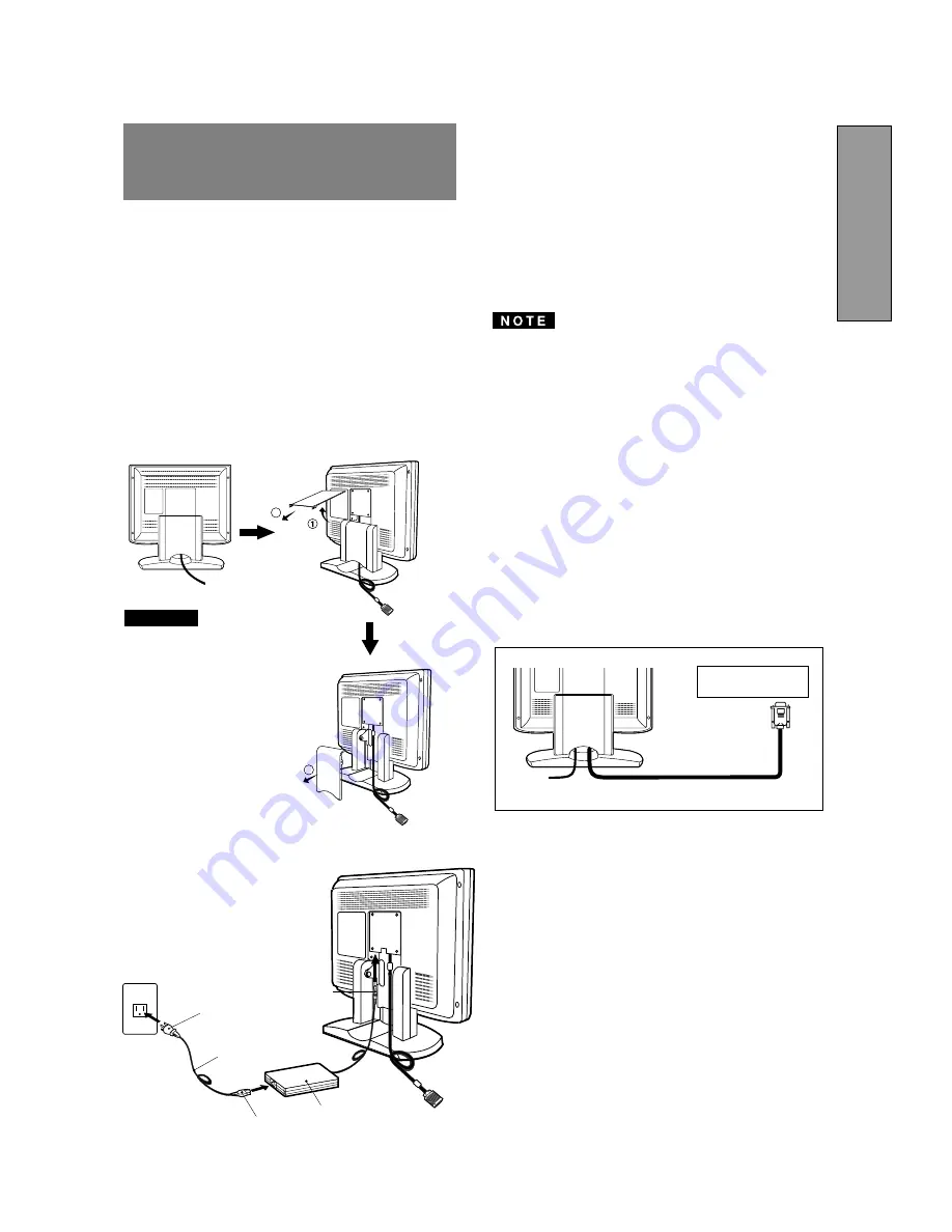
Figure 5 shows the signal cable connection to the Video
Graphics Array (VGA) port in an IBM Personal System/2
®
or any VGA compatible system.
1. Power off, the monitor and the computer.
2. Connect the one end of the signal cable to the 15-pin
connector on the VGA controller card.
3. Power on the monitor, then the computer.
4. After using the system, power off the monitor, then the
computer.
On the back of the monitor are three plug-in connec-
tions: one for the DC power connection and others for
the video signal connection.
3.1
AC Power Connection
Remove the cable covers. The DC jack from the AC
Adapter is connected into the DC power connector on the
back of the monitor. One end of the power cord is
connected into the AC Adapter, and another end of the
power cord is plugged into a AC outlet. The monitor’s auto-
sensing AC Adapter can automatically follow the AC input.
The socket-outlet shall be
installed near the equipment
and shall be easily acces-
sible. During servicing, dis-
connect the plug from the
socket-outlet.
Do not use this AC Adapter
to other equipments, as this
can cause a fire.
When operating the LCD
monitor with its AC220-240V
worldwide power supply,use
a power supply cord that
matches the power supply
voltage of the AC power
outlet being used.The power
supply cord you use must
have been approved by and
comply with the safety stan-
dards of your country.
Plug
CAUTION
Power Cord
Receptacle
AC Adapter
DC Jack
<How to remove the covers>
3
2
3
3
INSTALLATION AND
CONNECTION


