background image

Index

Warning, Caution ..........................................................................................................................English-1

Intended Use ................................................................................................................................English-2

Registration Information ...............................................................................................................English-3

Recommended use ......................................................................................................................English-4

Contents .......................................................................................................................................English-6

Quick Start ....................................................................................................................................English-7

Controls ........................................................................................................................................English-12

Using the PICTURE MODE function ............................................................................................English-16

Quick screen QA test function ......................................................................................................English-16

Advanced OSD .............................................................................................................................English-17

Specifi cations ...............................................................................................................................English-21

Features .......................................................................................................................................English-22

Troubleshooting ............................................................................................................................English-23

STAND-ALONE CALIBRATION ...................................................................................................English-24

Self Calibration .............................................................................................................................English-25

Copy Calibration ...........................................................................................................................English-26

Gamma Adjust ..............................................................................................................................English-27

DICOM Measurement ..................................................................................................................English-28

AMBIENT SENSOR CALIBRATION .............................................................................................English-28

Manufacturer’s Recycling and Energy Information .......................................................................English-30

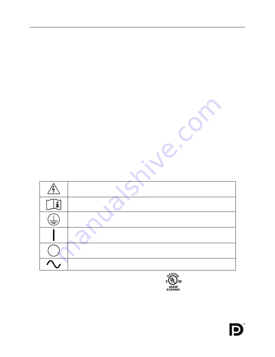
Symbol Information

This symbol warns user that uninsulated voltage within the unit may have suffi cient magnitude to 
cause electric shock. Therefore, it is dangerous to make any kind of contact with any part inside 
this unit.

This symbol alerts the user that important literature concerning the operation and maintenance of 
this unit has been included. Therefore, it should be read carefully in order to avoid any problems.

Protective earth terminal marked.

Main switch ON.

Main switch OFF.

AC Input.

MEDICAL - GENERAL MEDICAL EQUIPMENT
AS TO ELECTRICAL SHOCK, FIRE AND MECHANICAL 
HAZARD ONLY IN ACCORDANCE WITH ANSI/AAMI 
ES60601-1:2005 AND CAN/CSA-C22.2 NO.60601-1:08
ALSO LISTED ACCORDANCE WITH UL 60950-1 AND
CAN/CSA-C22.2 NO.60950-1-07
45VU
E332883

UL MARK CERTIFICATION, ANSI/AAMI ES60601-1:2005
cUL, CAN/CSA-C22.2 NO.60601-1:08

Windows is a registered trademark of Microsoft Corporation. NEC is a registered trademark of NEC Corporation.
ErgoDesign is a registered trademark of NEC Display Solutions, Ltd. in Austria, Benelux, Denmark, France, 
Germany, Italy, Norway, Spain, Sweden, U.K.
All other brands and product names are trademarks or registered trademarks of their respective owners.
The DisplayPort Icon is a trademark of the Video Electronics Standards Association, registered in the U.S. 
and other countries.

Содержание MD211G3

Страница 1: ...MD211G3 INSTALLATION MAINTENANCE GUIDE ...

Страница 2: ...user that important literature concerning the operation and maintenance of this unit has been included Therefore it should be read carefully in order to avoid any problems Protective earth terminal marked Main switch ON Main switch OFF AC Input MEDICAL GENERAL MEDICAL EQUIPMENT AS TO ELECTRICAL SHOCK FIRE AND MECHANICAL HAZARD ONLY IN ACCORDANCE WITH ANSI AAMI ES60601 1 2005 AND CAN CSA C22 2 NO 6...

Страница 3: ... REFER SERVICING TO QUALIFIED SERVICE PERSONNEL CAUTION Power Cord Important Information CAUTION Please use the power cord provided with this monitor in accordance with the table below If a power cord is not supplied with this equipment please contact your supplier For all other cases please use a power cord that matches the AC voltage of the power outlet and has been approved by and complies with...

Страница 4: ...oms is not recommended if cleaning of the air intakes from dust and textile lint in regular time intervals cannot be performed by the user maximum interval six months This device is equipped with an integrated front sensor and ambient light sensor complying with the IEC 62563 1 standard requirements for measurement devices with a calibration traceable to a primary standards laboratory Therefore th...

Страница 5: ...ur in a particular installation If this equipment does cause harmful interference to radio or television reception which can be determined by turning the equipment off and on the user is encouraged to try to correct the interference by one or more of the following measures Reorient or relocate the receiving antenna Increase the separation between the equipment and receiver Connect the equipment in...

Страница 6: ...not install where the monitor will be exposed to continual vibration If monitor or glass is broken do not come in contact with the liquid crystal and handle with care To prevent damage to the LCD monitor caused by tipping over due to earthquakes or other shocks make sure to install the monitor in a stable location and take measures to prevent falling Please do not touch patient and this medical de...

Страница 7: ... MONITOR For optimum performance allow 30 minutes for the monitor to warm up Adjust the monitor height so that the top of the screen is at or slightly below eye level Your eyes should look slightly downward when viewing the middle of the screen Position your monitor no closer than 40 cm 15 75 inches and no further away than 70 cm 27 56 inches from your eyes The optimal distance is 50 cm 19 69 inch...

Страница 8: ...1 DisplayPort cable CD ROM x 2 Power Cord 2 Quick Reference Guide USB Cable Remember to save your original box and packing material to transport or ship the monitor 1 Dual link DVI cable 2 Type and number of power cords included will depend on the where the LCD monitor is to be shipped When more than one power cord is included please use a power cord that matches the AC voltage of the power outlet...

Страница 9: ...onnect the DisplayPort cable to the connector of the display controller in your system Figure A 2 Figure A 1 Figure A 2 DisplayPort cable NOTE 1 Please use a DisplayPort cable with a DisplayPort logo 2 When removing the DisplayPort cable hold down the top button to release the lock 3 Height adjustment is locked by a lock button Place hand on top of the monitor stand to push down the screen to the ...

Страница 10: ...5 sub monitors can be daisy chained Figure C 1 Highest Stand Position Power cord 30 Tilt Figure C 1a A Type B Type A Type B Type Sensor Port 1 DVI D Cable DisplayPort Cable USB Upstream Port USB Downstream Port 5 To keep the cables neatly organized place them into the cable management system that is built into the stand Place the cables in the hooks firmly and evenly Figure C 2 and Figure C 3 6 Pl...

Страница 11: ...r switch on the top Portrait or left side Landscape of the monitor Figure E 1 Turn on the computer NOTE If you have any problems please refer to the Troubleshooting section of this Manual Figure E 1 Power switch Raise and Lower Monitor Screen The monitor may be raised or lowered in either Portrait or Landscape mode To raise or lower the screen place hands on each side of the monitor and lift or lo...

Страница 12: ... screen place hands on each side of the monitor and turn clockwise from Landscape to Portrait or counter clockwise from Portrait to Landscape Figure R 1 To rotate the OSD menu between landscape and portrait refer to Controls section Figure R 1 Tilt Grasp both sides of the monitor with your hands and adjust the tilt as desired Figure TS 1 Figure TS 1 NOTE Handle with care when tilting the monitor S...

Страница 13: ...able with the front sensor situated off the edge Figure S 2 5 Slide the cable cover up NOTE The cable cover is not removable 6 Place hand on the back side of the monitor and lift up the stand 7 Remove the 4 screws connecting the monitor to the stand Remove 2 bottom screws first Figure S 2 8 Lower the stand and slide the cable cover down 9 Remove 2 top screws Figure S 3 Reverse process to re attach...

Страница 14: ...Exits any OSD sub menu Exits the OSD Control menu Shows OSD menu Shows PICTURE MODE Selects the item Changes the input source Resets the OSD back to factory settings Shows the quick screen QA test pattern 2 LED Indicates that power is on 3 Control Buttons A RESET button NOTE When not in the OSD control menu press the RESET button for at least 3 seconds to display the quick screen QA test pattern g...

Страница 15: ...TURE MODE Change to a picture mode which is most suitable for the type of content that is shown You can choose one of two possible PICTURE MODES See Advanced OSD menu Tag1 PICTURE MODE page 17 and Using the PICTURE MODE function page 16 for more information Tools SHARPNESS This function is digitally capable of keeping a crisp image at any time It is continuously adjustable to get as distinct or as...

Страница 16: ...itor will automatically return to normal mode QA TEST Provides a quick daily visual image quality check of this diagnostic monitor by just using a button on the monitor MENU Tools LANGUAGE The OSD control menus are available in nine languages OSD LEFT RIGHT You can choose where you would like the OSD control menu to appear on your screen Selecting OSD Location allows you to manually adjust the pos...

Страница 17: ...ives a warning when there is no Horizontal or Vertical Sync After power is turned on or when there is a change of input signal the No Signal message window will appear OUT OF RANGE This function gives a recommendation of the optimized resolution and refresh rate After power is turned on or there is a change of input signal or if the video signal doesn t have proper timing the Out Of Range message ...

Страница 18: ...DF ERROR result in is a quick indicator of the gray level quality against the ideal DICOM curve Depending on the QA standard which is used in your country different GSDF error limits may exist Please compare the actual result with your local regulations or guidelines You may now check the gray levels and the overall quality visually To exit the QA TEST mode press EXIT The image of the video signal...

Страница 19: ...um by a monitor Gamma is defined by the relationship between the signal input voltage and the resulting intensity of the monitor s light output A perfect linear device would have a Gamma of 1 0 A Gamma correction to DICOM Part 14 is used to alter the luminance output of a monitor to gray steps which appear linear to the human visual system CUSTOM VALUE CUSTOM VALUE can be adjusted when CUSTOM is s...

Страница 20: ... RIGHT to select FIRST When current video input signal is not present then the monitor searches for a video signal from a different video source If a video signal is supplied by the other video source the monitor automatically switches to the new video source The monitor will not look for any other video signals as long as the current video signal is present LAST When the monitor is displaying a s...

Страница 21: ...e a screen will appear indicating the OSD controls are locked out There are three types of OSD LOCK OUT OSD LOCK OUT with no control To activate the OSD Lock Out function press SELECT then RIGHT button and hold down simultaneously To deactivate the OSD Lock Out press SELECT then RIGHT button and hold down simultaneously while in the OSD menu No controls can be adjusted while in the lock out mode O...

Страница 22: ...by a sensor LANDSCAPE The preferred timing is fixed to landscape orientation 2048x1536 pixels PORTRAIT The preferred timing is fixed to portrait orientation 1536x2048 pixels Note If you have any problems please refer to the Troubleshooting section of this Manual If a change was made in EDID SELECTION the connected computer must be restarted to recognize this change DDC CI DDC CI ENABLE DISABLE Tur...

Страница 23: ...al display performance Active Display Area Landscape Horiz Vert Portrait Horiz Vert 433 2 mm 17 1 inches 324 9 mm 12 8 inches 324 9 mm 12 8 inches 433 2 mm 17 1 inches USB Hub I F Port Load Current USB Specification Revision 2 0 Upstream 1 Downstream 2 Maximum 0 5A per port Power Supply AC 100 240 V 50 60 Hz Current Rating 1 2 0 46 A For Mexico 2 0A Dimensions Landscape Portrait Height Adjustment ...

Страница 24: ...olutions supported directly to your computer automatically optimizing display performance Intelligent Power Manager System Provides innovative power saving methods that allow the monitor to switch to a lower power consumption level when on but not in use saving two thirds of your monitor energy costs reducing emissions and extending the useful life of the monitor s backlights Multiple Frequency Te...

Страница 25: ...our to erase the image NOTE As with all personal display devices NEC DISPLAY SOLUTIONS recommends using a moving screen saver at regular intervals whenever the screen is idle or turning off the monitor when not in use Message OUT OF RANGE is displayed screen is either blank or shows rough images only Image is displayed only roughly pixels are missing and OSD warning OUT OF RANGE is displayed Eithe...

Страница 26: ...ppear on screen Figure A 1 When Stand Alone Calibration is executed the message window will appear Figure A 3 and the screen becomes dark for about 10 seconds Then ZERO CALIBRATION will start automatically NOTE Please only use an USB optical sensor according to our specification Refer to the KEY MAP Figure A 2 to adjust the settings for calibration Stand Alone calibration should be performed in ei...

Страница 27: ...e S 3 Press SELECT to go to the next section To select AUTO CALIB go to step 6 To select EXPERT CALIB go to step 7 AUTO CALIB Make sure that the USB optical sensor is connected to the sensor port 6 The procedure will ask for the USB optical sensor to be placed on the center of the display panel Figure S 4 Tilt the display panel approximately 5 backward and place the USB optical sensor in the cente...

Страница 28: ...on 5 The procedure will ask for the USB optical sensor to be placed on the center of the display panel Figure C 4 Tilt the display panel approximately 5 backward and place the USB optical sensor in the center of the display panel Figure C 1 NOTE Place the USB optical sensor flat against the display A to avoid any influence of ambient light Do not press the USB optical sensor against the display pa...

Страница 29: ... the advanced menu page 24 2 Select GAMMA ADJUST in the MODE selection Figure 1 3 Select the target UNIFORMITY Press SELECT to go to the next section 4 Set the target LUMINANCE cd m2 Figure 2 Press SELECT to start the calibration This may take several minutes depending on user setting Figure 2 Figure 1 5 DICOM Measurement is continuously executed automatically After completing DICOM Measurement yo...

Страница 30: ...7 setting is 1 or 2 Please perform AMBIENT SENSOR CALIBRATION in the following cases The usage environment has changed AMBIENT SENSOR CALIBRATION requires an illuminance meter and a telescopic luminance meter 1 In power off mode measure the luminance value of the center of the screen by the telescopic luminance meter If a telescopic luminance meter is not available go to next step 2 Turn on the di...

Страница 31: ...having measured press SELECT without changing the value 6 After the CALIBRATION SUCCEEDED message appears Figure AS 4 press SELECT You can set DATE and TIME by using control keys and press SELECT 7 To end the calibration mode press EXIT Figure AS 4 Figure AS 3 Figure AS 5 Illuminance meter ...

Страница 32: ...gement Signalling DPMS Standard signal is sent to the monitor the Energy Saving mode is activated The monitor enters a single Energy Saving mode Mode Power consumption LED colour Normal Operation Approx 105 W Green Energy Saving Mode Less than 2 W Amber Off Mode Less than 1 W Unlit WEEE Mark European Directive 2002 96 EC Within the European Union EU wide legislation as implemented in each Member S...

Отзывы: