background image

English

 - 124

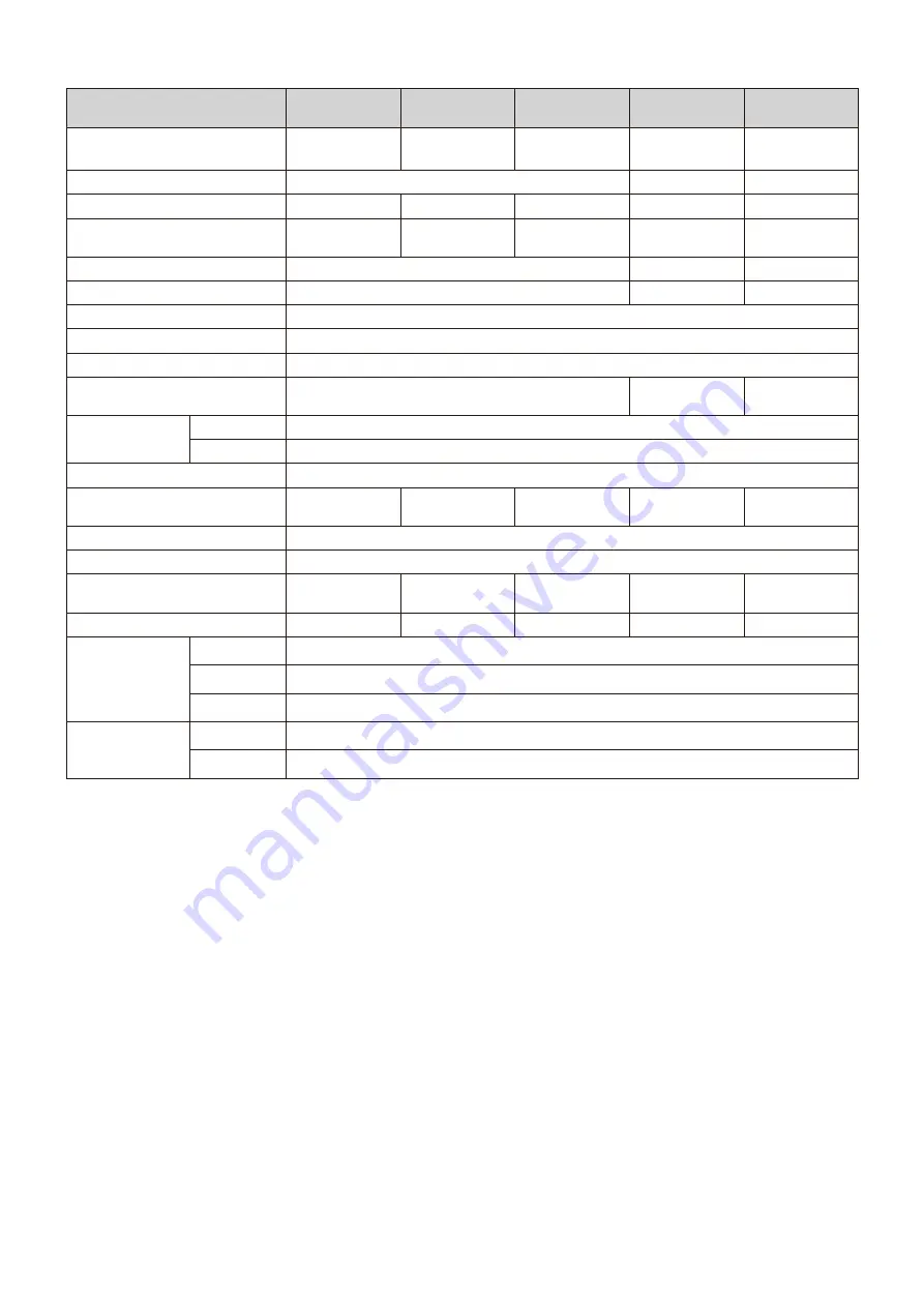
LED-FE012i2-110/ 

LED-FE012i2-11N

LED-FE019i2-110/ 

LED-FE019i2-11N

LED-FE015i2-137/ 

LED-FE015i2-13N

LED-FE009i2-165/ 

LED-FA009i2-16N

LED-FE019i2-165/ 

LED-FE019i2-16N

Module configuration

LED-FE012i2

4×4

LED-FE019i2

4×4

LED-FE015i2

5×5

LED-FE009i2

6×6

LED-FE019i2

6×6

LED configuration

3in1 SMD

4in1 SMD (IMD)

3in1 SMD

Pixel pitch

1.27 mm

1.90 mm

1.58 mm

0.95 mm

1.90 mm

Number of displayed pixels 

(resolution/module)

1920 × 1080

1280 × 720

1920 × 1080

3840 × 2160

1920 × 1080

Brightness

700 cd/m2

600 cd/m2

700 cd/m2

Contrast ratio

4000:1

5000:1

4000:1

Brightness adjustment range

0 to 100% (256 increments)

Gamma correction

1.0 to 4.0 (default setting: 2.8)

Color temperature

3000 K to 9500 K (default setting: 6500 K)

Viewing angle

Up 80°, Down 80°, Left 80°, Right 80°

Up 70°, Down 70°, 

Left 70°, Right 70°

Up 80°, Down 80°, 

Left 80°, Right 80°

Signal interface

Signal input

1×RJ-45

Signal output

1×RJ-45

Power supply

100 V AC to 240 V AC, 50 Hz/60 Hz

Power consumption (all white, 

100% brightness)

2000 W

2000 W

3125 W

5400 W

4500 W

IP rating

Front IP20 / Rear IP20

Maintenance

Front

Dimensions

2444×1475.5× 

78 mm

2444×1475.5× 

78 mm

3052×1817.5× 

78 mm

3660×2159.5× 

78 mm

3660×2159.5× 

78 mm

Weight

182 kg

182 kg

279 kg

390.8 kg

390.8 kg

Operating 

environment

Temperature

-20 to 40°C

Humidity

10% to 80% (without condensation)

Altitude

No more than 5000 m

Storage 

environment

Temperature

-20 to 45°C

Humidity

10% to 85% (without condensation)

Specifications are subject to change without notice.

Содержание FA Series

Страница 1: ...indoor use LED FA012i2 110 LED FA019i2 110 LED FA015i2 137 LED FA009i2 165 LED FA019i2 165 LED FA012i2 220 LED FA025i2 220 LED FA038i2 220 LED FE012i2 110 LED FE019i2 110 LED FE015i2 137 LED FE009i2...

Страница 2: ...colors on a part of the screen 88 3 State monitoring using the software 94 4 Redundancy setting method 99 Specifications FA series English 117 Specifications FE series English 121 Diagram English 127...

Страница 3: ...ghly before reading this manual WARNING Failing to heed this symbol and handling the product incorrectly could result in accidents leading to major injury or death CAUTION Failing to heed this symbol...

Страница 4: ...immediately ask a technician or your retailer for repair Install the product so that the vents are not obstructed Make sure there are enough people available to ensure safety at least two people when...

Страница 5: ...used indoors Do not use it outdoors Otherwise it may cause a malfunction Do not use or store the product in the following places Near heaters Places with lots of humidity or dust or places subject to...

Страница 6: ...retained the temperature will rise very quickly and the water inside the lamps will evaporate and expand This will cause the encapsulating resin to expand which may lead to separation of the boundary...

Страница 7: ...AC power is input into 5 AC power is output from 6 When AC power is input into 6 AC power is output from 5 Do not input AC power into both 5 and 6 7 Status lamp red Lights up when power is on 8 Status...

Страница 8: ...t from 3 Do not input AC power into both 3 and 4 5 Status lamp red Lights up when power is on 6 Status lamp blue Not functioning with this device 7 Status lamp green Flashes at intervals of approximat...

Страница 9: ...no connectors on the top side There are no guide pins FA series FE series PS 2 PS 2 RV Slave RV Master Power hub board Power unit Receiving card Power hub board 3 When connecting a LAN cable from the...

Страница 10: ...E015i2 EFN 6 X 6 frame set 0 9mm pitch LED FA009i2 165 LED FA009i2 16N LED FE009i2 165 LED FA009i2 16N 6 X 6 frame set 1 9mm pitch LED FA019i2 165 LED FA019i2 16N LED FE019i2 165 LED FE019i2 16N LED F...

Страница 11: ...thickness 5 mm M8 external dental pattern axis length 17 mm stainless steel color 35 30 5 1 45 40 5 1 75 70 5 1 75 70 5 1 1 Power bar cover plate 1 1 1 1 2 Power bar screw M8 20 Hexagon socket head s...

Страница 12: ...ad screw 45 40 5 1 53 48 5 1 61 56 5 1 61 56 5 1 Screw for connecting cabinets M8 25 53 48 5 1 85 80 5 1 125 120 5 1 125 120 5 1 LAN cable for the LED modules FA series 120 mm 12 20 18 30 135 mm 12 20...

Страница 13: ...3 3 1 Spare parts 2 Kit model only except for LED FA012i2 11N LED FA019i2 11N LED FA015i2 13N LED FA009i2 16N LED FA019i2 16N LED FA012i2 22N LED FA025i2 22N LED FA038i2 22N LED FE012i2 11N LED FE019i...

Страница 14: ...ernal dental pattern axis length 17 mm stainless steel color 113 108 5 1 113 108 5 1 113 108 5 1 1 Power bar cover plate 2 2 2 2 Power bar screw M8 20 Hexagon socket head screw 29 24 5 1 29 24 5 1 29...

Страница 15: ...2 5 1 77 72 5 1 Screw for connecting cabinets M8 25 229 224 5 1 229 224 5 1 229 224 5 1 LAN cable for the LED modules FA series 120 mm 48 56 56 135 mm 48 56 56 1 m 8 8 LAN cable for the LED modules FE...

Страница 16: ...Spare parts 2 Kit model only except for LED FA012i2 11N LED FA019i2 11N LED FA015i2 13N LED FA009i2 16N LED FA019i2 16N LED FA012i2 22N LED FA025i2 22N LED FA038i2 22N LED FE012i2 11N LED FE019i2 11N...

Страница 17: ...English 15 8 x 8 frame set...

Страница 18: ...ctors on the hub board and pixel card Adhesion of dust or dirt to the connectors may cause poor contact leading to abnormalities of video display When installing the product in a narrow place in a wal...

Страница 19: ...oor 500 mm 500 mm Depending on the temperature condition Wall mounting setting D E 40 C D E Recommended distance to ceiling Recommended distance to floor 500 mm 500 mm Depending on the temperature con...

Страница 20: ...he work has been completed 3 Mark the positions of the anchor points on the wall Mark the positions of the holes you will make for the anchor points refer to the figures below and the Anchor points nu...

Страница 21: ...x 5 frame set 684 mm 684 mm 608 mm 608 mm 608 mm Anchor points positions 6 x 6 frame set 608 mm 608 mm 608 mm 608 mm 1026 mm 684 mm Anchor points positions 8 x 8 frame set 684 mm 684 mm 684 mm 342 mm...

Страница 22: ...Vertical distance 1026 mm 684 mm equally Distance top row middle row 1026 mm Distance middle row bottom row 684 mm Distance Bottom row 342 mm others 684 mm equally Anchor size 10 mm 10 mm 10 mm 10 mm...

Страница 23: ...ing mounting bar connector Insert the mounting bar connector and tighten it securely with 6 screws M6 x 14 Removing mounting bar connector Remove the 6 screws M6 x 14 holding the mounting bar connecto...

Страница 24: ...l the mounting bars on the anchor points on the wall 2 Check the distance between the mounting bars using the alignment bars 4 x 4 frame set 608 mm 608 mm Alignment bar Alignment bar 5 x 5 frame set A...

Страница 25: ...English 23 6 x 6 frame set 608 mm 608 mm 608 mm 608 mm Alignment bar Alignment bar 8 x 8 frame set 1216 mm 608 mm 608 mm 608 mm 608 mm Alignment bar Alignment bar...

Страница 26: ...he positions if required Wall mounted Mounting bar installation 4 x 4 frame set M10 screws 7 Install the power bar Remove the power bar cover and install the power bar using Power bar screw M8 screws...

Страница 27: ...English 25 Power bar Power bar screw M8 When using the 8 x 8 frame set use the power bar connecting part to install the power bar...

Страница 28: ...pitch of the screws is no longer visible Hanger pin LED cabinet M8 8 mm Hanger pin Cabinet hanger pins installation position 4 x 4 frame set 5 x 5 frame set Cabinet Power bar Mounting bar Positions f...

Страница 29: ...English 27 8 x 8 frame set Cabinet Power bar Mounting bar Mounting bar Positions for Cabinet hanger pins...

Страница 30: ...serted into the cabinets into the holes on the mounting bars starting from the lowest row Fix temporarily the cabinets of the first row to the power bar Check that the top edges of any two adjacent ca...

Страница 31: ...tighten the screws completely After you have installed two rows of cabinets align the surfaces of the cabinets using the Adjustment plates Adjust the position of the cabinet by turning the vertical al...

Страница 32: ...the next row of cabinets and align their surfaces Connect the power cord and the LAN cable from the opening at the back of the power bar How to connect the power cord FA series C2 C1 C B D2 D1 A L N...

Страница 33: ...t in Power bar D Data cable WARNING Pay attention to the wire colors of the power cord when connecting the cord If the cables are not connected correctly it may lead to a fire or an electrical shock B...

Страница 34: ...overframe and align it with the marking line and fix them with screw for overframe screws Use overframe screws M4 x 4 for the right side and overframe screws M4 x 8 for the rest Install the corner par...

Страница 35: ...English 33 Slot nut installation locations 8 x 8 frame set 5 x 5 frame set 4 x 4 frame set 6 x 6 frame set Screw for overframe M4 4 Screw for overframe M4 8...

Страница 36: ...475 5 800 698 5 608 608 Through hole for the LAN cable and power code 608 608 608 360 260 78 2444 2432 5 x 5 frame set B A A A A B A A A A B A A A A B A A A A B A A A A 1811 5 1811 5 1710 1817 5 800 6...

Страница 37: ...71 608 608 608 608 3648 3660 608 608 608 608 608 260 360 78 Through hole for the LAN cable and power code 6 x 6 frame set 0 9 mm pitch B A A A A A B A A A A A B A A A A A B A A A A A B A A A A A B A A...

Страница 38: ...608 608 608 1216 4864 4876 608 608 608 608 608 608 608 260 360 78 Through hole for the LAN cable and power code 8 x 8 frame set 1 2 mm pitch B A A A A A A A B A A A A A A A B A A A A A A A B A A A A A...

Страница 39: ...ts to the frame as shown in the figure below Use screws with a length adapted to the cabinet thickness 30 mm Use also brackets with a sufficient thickness to hold the screws 48 mm 88 mm 30 mm 4 M6 Ple...

Страница 40: ...sing Ask a technician or your retailer for more details 2 Maximum number of power connections CAUTION Exceeding the maximum capacity may generate smoke or cause a fire Check the voltage used and do no...

Страница 41: ...LED FA031i2 10 modules 20 modules LED FA038i2 10 modules 20 modules LED FA009i2 8 modules 14 modules Product name 100 120 V AC 200 240 V AC LED FE009i2 10 modules 18 modules LED FE012i2 10 modules 20...

Страница 42: ...the capacity of the switchboard and the inrush current specification FA series 4 x 4 frame set HDMI DVI AC POWER Controller MCTRL660Pro Controller MCTRL660Pro 4 4 frame set AC 100V AC 200V Number of p...

Страница 43: ...stem 3 3 Current rating per 1 module 1 5 A 0 8 A per power system 7 5 A 1 System 15 0 A 2 Systems 4 0 A 1 System 8 0 A 2 Systems per frame set 37 5 A 20 0 A Inrush current per 1 module 100 A 200 A 25...

Страница 44: ...660Pro Controller MCTRL660Pro 6 6 frame set 0 9 mm pitch AC 100V AC 200V Number of power system 3 3 Current rating per 1 module 2 0 A 1 1 A per power system 24 0 A 13 2 A per frame set 72 0 A 39 6 A I...

Страница 45: ...ro 6 6 frame set 1 9 mm pitch AC 100V AC 200V Number of power system 3 3 Current rating per 1 module 1 5 A 0 8 A per power system 18 0 A 9 6 A per frame set 54 0 A 28 8 A Inrush current per 1 module 1...

Страница 46: ...DVI 8 8 frame set 1 2 mm pitch AC 100V AC 200V Number of power system 8 8 Current rating per 1 module 1 5 A 0 8 A per power system 12 0 A 6 4 A per frame set 96 0 A 51 2 A Inrush current per 1 module...

Страница 47: ...MI DVI 8 8 frame set 2 5 mm pitch 3 8 mm pitch AC 100V AC 200V Number of power system 8 8 Current rating per 1 module 1 5 A 0 8 A per power system 12 0 A 6 4 A per frame set 96 0 A 51 2 A Inrush curre...

Страница 48: ...4 frame set AC 100V AC 200V Number of power system 2 2 Current rating per 1 module 1 5 A 0 8 A per power system 12 0 A 6 4 A per frame set 24 0 A 12 8 A Inrush current per 1 module 50 A 100 A 25 C Col...

Страница 49: ...urrent rating per 1 module 1 5 A 0 8 A per power system 7 5 A 1 System 15 0 A 2 Systems 4 0 A 1 System 8 0 A 2 Systems per frame set 37 5 A 20 0 A Inrush current per 1 module 50 A 100 A 25 C Cold star...

Страница 50: ...DVI 6 6 frame set 0 9 mm pitch AC 100V AC 200V Number of power system 3 3 Current rating per 1 module 2 0 A 1 1 A per power system 24 0 A 13 2 A per frame set 72 0 A 39 6 A Inrush current per 1 modul...

Страница 51: ...e set 1 9 mm pitch AC 100V AC 200V Number of power system 3 3 Current rating per 1 module 1 5 A 0 8 A per power system 18 0 A 9 6 A per frame set 54 0 A 28 8 A Inrush current per 1 module 50 A 100 A 2...

Страница 52: ...set 1 2 mm pitch AC 100V AC 200V Number of power system 8 4 Current rating per 1 module 1 5 A 0 8 A per power system 12 0 A 6 4 A per frame set 96 0 A 51 2 A Inrush current per 1 module 50 A 100 A 25...

Страница 53: ...2 5 mm pitch 3 8 mm pitch AC 100V AC 200V Number of power system 8 4 Current rating per 1 module 1 5 A 0 8 A per power system 12 0 A 6 4 A per frame set 96 0 A 51 2 A Inrush current per 1 module 50 A...

Страница 54: ...and power cords backside hole If the hole is not drilled place a flathead screwdriver from inside the cabinet at the edge of the round recess and tap it lightly with a hammer to make a hole Cables fo...

Страница 55: ...o the backside hole of the cabinet and attach the cable holder fixing ring from the outside of the cabinet Insert the cables Pinch the cable with the cable fixing part and attach it to the cable holde...

Страница 56: ...he connector with the core wires being sinuous CAUTION Be sure to peel off the wire sheath over the specified length 10 to 12 mm Lever operation is necessary even for connection of a solid core wire 2...

Страница 57: ...at generation Power code connection checking Perform checking for correct and proper connection Lightly pull on the wires one by one to check that they will not be pulled out Check visually WARNING Pa...

Страница 58: ...sh 56 4 LAN cable connection Connect the LAN cables for the signal between the LED modules Use the through holes to pass the cables between the modules Four through holes for the LAN cables LAN connec...

Страница 59: ...the slave connectors to the slave connectors Hub board Insert the LAN cables into the through hole and connect it to the LAN connectors LAN cable from the LED controller 120 mm 135 mm LAN cable from...

Страница 60: ...ard when installing the pixel cards When installing the pixel cards pay attention not to damage them against the pixel cards already installed or other objects Otherwise the video may not be displayed...

Страница 61: ...stall the pixel card into the cabinet with the four guide holes of the pixel card aligned with the four guide pins of the cabinet four pins for each pixel card The pixel card is secured by the 4 magne...

Страница 62: ...ion to the wire colors of the power cord when connecting the cord If the cables are not connected correctly it may lead to a fire or an electrical shock Blue N Brown L Yellow green Ground CAUTION When...

Страница 63: ...e file different than the one in the supplied USB drive may lead to malfunction Log in with the administrator privileges Display the login screen as follows User U Advanced Synchronous System UserLogi...

Страница 64: ...hat is displayed select the Screen Connection tab a a CAUTION Do not change the settings in the Receiving Card tab Otherwise the video may not be displayed properly Select Standard Screen under Screen...

Страница 65: ...80 Product name LED FA025i2 LED FE025i2 LED FA031i2 LED FE031i2 LED FA038i2 LED FE038i2 Pixel pitch 2 5 mm 3 1 mm 3 8 mm Number of displayed pixels resolution module Width 240 Height 135 Width 192 Hei...

Страница 66: ...to the values e 2 Since the configuration is 4 columns x 4 rows enter Columns 4 and Rows 4 A 4 columns x 4 rows screen configuration is displayed 3 If multiple LED controllers are used select the num...

Страница 67: ...rt 1 of the LED controller Select 1 port 1 under Ethernet Port No d Select the cabinet at the bottom left with the mouse and then select the other cabinets up to the top cabinet Then select Port2 and...

Страница 68: ...t the process finished successfully is displayed click OK b Check that the image is correctly displayed and then click the Save button i When the screen indicating that the process finished successful...

Страница 69: ...ving Card tab a c d b a 2 Click Load from File b 3 Select the configuration file rcfgx file you want to load to the receiving card A screen like the following appears when the loading process is compl...

Страница 70: ...English 68 Update the Calibration Data 1 Login as Advanced User 2 Click the Calibration button a Start calibration menu a 3 Select the Screen1 radio button 4 Click on the Manage Coefficients tab b b...

Страница 71: ...his option when installing Module Flash Select by Topology or list Select this option when replacing pixel cards etc If Line calibration or Adjusting the colors on a part of the screen has been perfor...

Страница 72: ...k to main window by clicking X button 9 Check the calibration state in the bottom left corner of Screen Calibration window Enable Disable Calibration 10 If calibration setting Disable Calibration is c...

Страница 73: ...e Setting You can adjust the brightness the gamma correction value and the color temperature Click Brightness on the top screen to display the following window e c b d a Click Advanced Settings to exp...

Страница 74: ...Gamma correction Set the gamma correction value using the slider c Increasing the value makes the dark parts of the screen darker 3 Color temperature Set the color temperature using the slider d Incr...

Страница 75: ...abs at the top of the window click Tools Quickly Adjust Dark or Bright Lines Adjust Dark or Bright Lines 3 Click the Quickly Adjust New button on the right of the window that pops up 4 A screen like t...

Страница 76: ...de one module on the screen that pops up and then click OK LED FA009i2 LED FA012i2 LED FA012i2 SB LED FA015i2 LED FA015i2 SB LED FA019i2 LED FA031i2 LED FA038i2 LED FE009i2 LED FE012i2 LED FE015i2 LED...

Страница 77: ...FA012i2 LED FA012i2 SB LED FA015i2 LED FA015i2 SB LED FA019i2 LED FA031i2 LED FA038i2 LED FE009i2 LED FE012i2 LED FE015i2 LED FE019i2 LED FE031i2 LED FE038i2 LEDFE012i2 E LED FE015i2 E LED FE019i2 E 8...

Страница 78: ...A012i2 SB LED FA015i2 LED FA015i2 SB LED FA019i2 LED FA031i2 LED FA038i2 LED FE009i2 LED FE012i2 LED FE015i2 LED FE019i2 LED FE031i2 LED FE038i2 LEDFE012i2 E LED FE015i2 E LED FE019i2 E LED FA025i2 LE...

Страница 79: ...on the LED modules LED FA009i2 LED FA012i2 LED FA012i2 SB LED FA015i2 LED FA015i2 SB LED FA019i2 LED FA031i2 LED FA038i2 LED FE009i2 LED FE012i2 LED FE015i2 LED FE019i2 LED FE031i2 LED FE038i2 LEDFE0...

Страница 80: ...8i2 LED FE009i2 LED FE012i2 LED FE015i2 LED FE019i2 LED FE031i2 LED FE038i2 LEDFE012i2 E LED FE015i2 E LED FE019i2 E Upward arrow Increases the brightness makes the dark lines less noticeable Downward...

Страница 81: ...s complete click Save to HW at the bottom of the screen LED FA009i2 LED FA012i2 LED FA012i2 SB LED FA015i2 LED FA015i2 SB LED FA019i2 LED FA031i2 LED FA038i2 LED FE009i2 LED FE012i2 LED FE015i2 LED FE...

Страница 82: ...English 80 9 The adjustment is complete when the following screen is displayed Click Close to finish...

Страница 83: ...tallation environment Required tools example Soft brush animal hair brush to prevent static electricity Soft cloth that does not generate static electricity Air blower compressor Cleaning method a Tur...

Страница 84: ...e screws when removing loosening or setting tightening the screws Pay attention not to drop the screws and the other parts you have removed Pay attention not to lose the removed screws since they will...

Страница 85: ...tool is fully charged before starting the work Pixel card falls if the battery runs out Hold the pixel card with your hand to support in case it falls Do not turn the maintenance tool off until you ho...

Страница 86: ...Pay attention not to pull the hub board d Disconnect the cable from the hub board and then remove the hub board 4 positioning holes Status board Cabinet Hub board Remove the 16 screws Use a Phillips s...

Страница 87: ...ermal paste on the back of the power unit to be replaced Ask your retailer for more details on the types of thermal paste a Remove the hub board following the 1 Removing the hub board procedure on the...

Страница 88: ...securing the power unit Use a Phillips screwdriver No 2 The FE series power supply unit is only on the bottom side Replacing the receiving card Remove the receiving card from the hub board Remove the...

Страница 89: ...owing the procedure in the next section 2 State monitoring using the software No image is displayed on one pixel card Check that the contacts of the pixel card are correct contacts of the hub board Th...

Страница 90: ...he colors on a part of the screen 1 Log in with the administrator privileges English 61 2 Click Calibration a Start calibration menu a 3 Check that Chroma Calibration b is selected and click the Manag...

Страница 91: ...three available methods depending on the calibration range After setting the range click Next to display the Adjust Coefficients screen 5 1 Screen Adjust the entire frame set The calibration settings...

Страница 92: ...point top left of the selection range Width The horizontal distance from the points specified with Column Number and Row Number Height The vertical distance from the points specified with Column Numbe...

Страница 93: ...el card Width 160 Height 180 Width 120 Height 135 Width 96 Height 108 Width 80 Height 90 Product name LED FA025i2 LED FE025i2 LED FA031i2 LED FE031i2 LED FA038i2 LED FE038i2 Pixel pitch 2 5 mm 3 1 mm...

Страница 94: ...the display configuration is displayed Specify the range of the modules you want to adjust The calibration settings reading starts after Next is clicked The Adjust Coefficients screen is displayed whe...

Страница 95: ...green and blue parameters Click Next after you have finished the adjustment 8 Click Save to save the calibration settings you have adjusted 9 Click Finish to complete the procedure Note To return the...

Страница 96: ...monitoring the state of the system 3 1 Display under normal conditions The display is green under normal conditions Click Monitoring to check the state of the LED controller the operating state of th...

Страница 97: ...To display more details click Monitoring and then click Sending card on the screen that is displayed No video signal is being input to the LED controller Check that the LAN cable is connected Check th...

Страница 98: ...3rd column and the screen of the 2nd row 3rd column Check the internal LAN cable Problem with both power units of the screen of the 2nd row 3rd column Check the rear indicator red to see if it is lit...

Страница 99: ...details click Monitoring and then click Temperature on the screen that is displayed The LED modules with a high temperature are displayed in warm colors Since the internal temperature is high decreas...

Страница 100: ...English 98 4 Communication problem When the display is grey the communication is not established Check that the USB cable is connected Check that the LED controller is turned on...

Страница 101: ...left on the last module in the daisy chain connection HUB LED controllers LED modules Main Primary Backup For the MCTRL 4K LED controller the way to make connections is similar to this example LED E L...

Страница 102: ...d Backup controller separately Main Primary Backup On the Main Primary side Click the Restore Factory Settings button for initialization After initialization configure the settings for Select Input So...

Страница 103: ...the User s Manual Next select the Sending Card tab Go to Redundancy select the checkbox for Set as Primary and click Save On the Backup side Click the Restore Factory Settings button for initializatio...

Страница 104: ...f connection is the same as for Main Primary Next select the Sending Card tab Go to Redundancy select the checkbox for Set as Backup and click Save E End S Start Check the current brightness setting C...

Страница 105: ...English 103 The monitoring screens appear like below...

Страница 106: ...s configured as Main Primary Backup modules are displayed in green color which is an indication of normal state Main Primary modules are operating normally Main Primary Backup Modules connected to por...

Страница 107: ...English 105 In the case of MCTRL 4K the display of the LED controllers is as follows This example display is for the case of connection using four Ethernet cables Upper Backup Lower Main Primary...

Страница 108: ...last module in the daisy chain connection LED controllers LED modules Main Primary Backup For the MCTRL 4K LED controller the way to make connections is similar to this example LED E LED FE FC Start...

Страница 109: ...ng Card tab Click the Restore Factory Settings button for initialization After initialization configure the settings for Select Input Source and Source Configuration If the factory setting is correctl...

Страница 110: ...the User s Manual Notes on the setting operation Perform these setting procedures prior to the redundancy settings configuration Make sure that the value of Quantity of Screens is 1 To change a differ...

Страница 111: ...y Sending Card 1 Serial Number of Primary Port 1 Serial Number of Backup Sending Card 2 Serial Number of Backup Port 1 Serial Number of Primary Sending Card 1 Serial Number of Primary Port 2 Serial Nu...

Страница 112: ...10 Check the current brightness setting Click the Brightness button In the Brightness Adjustment screen set the desired brightness value and click the Save to HW button The monitoring screens appear l...

Страница 113: ...English 111 In the case of MCTRL 4K the display of the LED controllers is as follows This example display is for the case of connection using four Ethernet cables Upper Backup Lower Main Primary...

Страница 114: ...eft on the last module in the daisy chain connection LED controllers LED modules For the MCTRL 4K LED controller the way to make connections is similar to this example LED E LED FE FC Start the contro...

Страница 115: ...tings button for initialization After initialization configure the settings for Select Input Source and Source Configuration If the factory setting is correctly configured and the device connection is...

Страница 116: ...r s Manual E End S Start Notes on the setting operation Perform these setting procedures prior to the redundancy settings configuration Make sure that the value of Quantity of Screens is 1 To change a...

Страница 117: ...erial Number of Backup Sending Card 1 Serial Number of Backup Port 4 Serial Number of Primary Sending Card 1 Serial Number of Primary Port 2 Serial Number of Backup Sending Card 1 Serial Number of Bac...

Страница 118: ...16 Check the current brightness setting Click the Brightness button In the Brightness Adjustment screen set the desired brightness value and click the Save to HW button The monitoring screens appear l...

Страница 119: ...default setting 2 8 Color temperature 3000 K to 9500 K default setting 6500 K Viewing angle Up 85 Down 85 Left 85 Right 85 Up 70 Down 70 Left 80 Right 80 Signal interface Signal input 1 RJ 45 Signal...

Страница 120: ...temperature 3000 K to 9500 K default setting 6500 K Viewing angle Up 70 Down 70 Left 70 Right 70 Signal interface Signal input 1 RJ 45 Signal output 1 RJ 45 Power supply 100 V AC to 240 V AC 50 Hz 60...

Страница 121: ...default setting 2 8 Color temperature 3000 K to 9500 K default setting 6500 K Viewing angle Up 85 Down 85 Left 85 Right 85 Up 70 Down 70 Left 70 Right 70 Up 85 Down 85 Left 85 Right 85 Signal interfac...

Страница 122: ...temperature 3000 K to 9500 K default setting 6500 K Viewing angle Up 85 Down 85 Left 85 Right 85 Signal interface Signal input 1 RJ 45 Signal output 1 RJ 45 Power supply 100 V AC to 240 V AC 50 Hz 60...

Страница 123: ...default setting 2 8 Color temperature 3000 K to 9500 K default setting 6500 K Viewing angle Up 80 Down 80 Left 80 Right 80 Up 70 Down 70 Left 80 Right 80 Signal interface Signal input 1 RJ 45 Signal...

Страница 124: ...6500 K Viewing angle Up 70 Down 70 Left 70 Right 70 Signal interface Signal input 1 RJ 45 Signal output 1 RJ 45 Power supply 100 V AC to 240 V AC 50 Hz 60 Hz Power consumption all white 100 brightnes...

Страница 125: ...0 K to 9500 K default setting 6500 K Viewing angle Up 80 Down 80 Left 80 Right 80 Signal interface Signal input 1 RJ 45 Signal output 1 RJ 45 Power supply 100 V AC to 240 V AC 50 Hz 60 Hz Power consum...

Страница 126: ...to 4 0 default setting 2 8 Color temperature 3000 K to 9500 K default setting 6500 K Viewing angle Up 80 Down 80 Left 80 Right 80 Up 70 Down 70 Left 70 Right 70 Up 80 Down 80 Left 80 Right 80 Signal i...

Страница 127: ...ature 3000 K to 9500 K default setting 6500 K Viewing angle Up 80 Down 80 Left 80 Right 80 Up 70 Down 70 Left 80 Right 80 Signal interface Signal input 1 RJ 45 Signal output 1 RJ 45 Power supply 100 V...

Страница 128: ...ion 1 0 to 4 0 default setting 2 8 Color temperature 3000 K to 9500 K default setting 6500 K Viewing angle Up 80 Down 80 Left 80 Right 80 Signal interface Signal input 1 RJ 45 Signal output 1 RJ 45 Po...

Страница 129: ...ED FA012i2 SB LED FA015i2 LED FA015i2 SB LED FA019i2 LED FA031i2 LED FA038i2 LED FE009i2 LED FE012i2 LED FE015i2 LED FE019i2 LED FE031i2 LED FE038i2 LEDFE012i2 E LED FE015i2 E LED FE019i2 E 608 49 342...

Страница 130: ...English 128 LED FA025i2 LED FE025i2 608 49 342 Rear 4 x M8 18 5 24 24 44 44 520 294 Unit mm...

Страница 131: ...English 129 Adjustment plate 10 75 28 75 4 8 5 Unit mm...

Отзывы: