background image

1. Installing Internal Optional Devices 


Express5800/R110h-1  User’s Guide 

79

Chapter 2  Preparations 

1.13


3.5-inch Hard Disk Drive 

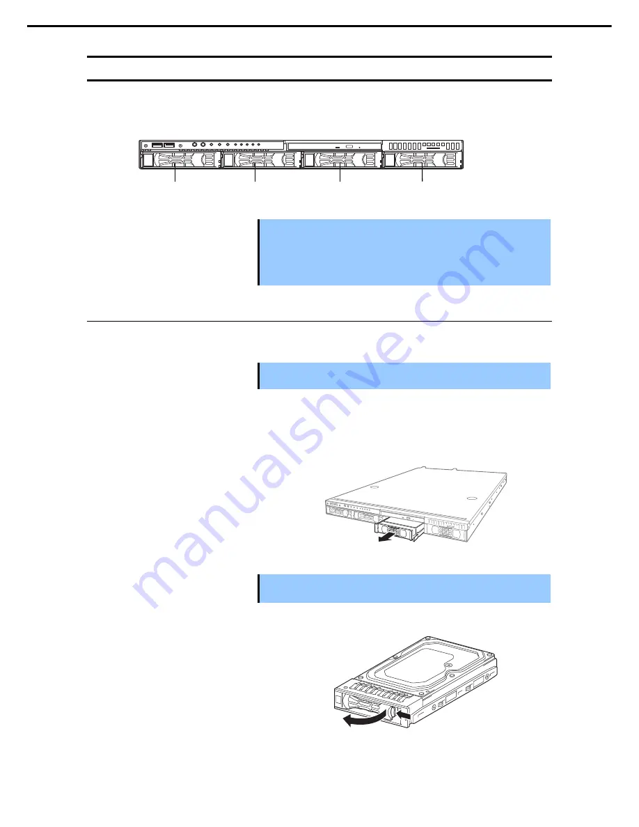
The hard disk drive bays can install up to four hard disk drives.   


Important 


Use hard disk drives provided by NEC.   


Hard disk drives with different types of interfaces or different rotational 
speeds cannot be installed together. 


If using hard disk drives in a RAID system, confirm the jumper settings and 
cabling. 


Installation 

1.13.1

Install a hard disk drive by using the following procedure.   


Important  In the RAID system, install the hard disk drives that have the same 

specifications (capacity, rotational speed and interface). 


 See 

Chapter 2 (1.2 Overview of Installation and Removal)

 for preparations. 

1.


Locate the slot where you install the hard disk drive.   

2.

The server provides four slots. Install hard disk drives in ascending order of slot number.   


Remove the dummy trays. 

3.


Important 


Keep the dummy trays for future use. 


Keep the dummy trays installed where hard disk drives are not installed. 


Unlock the handle of the tray. 

4.


Slot 0 

Slot 1 

Slot 3 

Slot 2 

Содержание Express5800/R110h-1

Страница 1: ...General Description Chapter 2 Preparations Chapter 3 Setup Chapter 4 Appendix NEC Express Server Express5800 Series Express5800 R110h 1 EXP335 335A User s Guide 10 111 03 101 01 January 2016 NEC Corporation 2016 ...

Страница 2: ...n of peripheral devices and suitable location for this server Chapter 3 Setup System BIOS configurations and summary of EXPRESSBUILDER Chapter 4 Appendix Specifications and other information Installation Guide Windows Chapter 1 Installing Windows Installation of Windows and drivers and precautions for installation Chapter 2 Installing the Bundled Software Installation of NEC ESMPRO Universal RAID ...

Страница 3: ...troduction 18 2 Accessories 19 3 Features 20 3 1 Firmware and Software Version Management 21 4 Names and Functions of Parts 22 4 1 Front View With Front Bezel 22 4 2 Front View Without Front Bezel 23 4 3 Rear View 25 4 4 External View 26 4 5 Internal View 27 4 6 Motherboard 31 4 7 Indicators 32 4 7 1 POWER LED 32 4 7 2 STATUS LED 1 2 32 4 7 3 LINK ACT LED 1 2 33 4 7 4 Optical Disk Access LED 33 4 ...

Страница 4: ...an unit 76 1 12 1 1 13 3 5 inch Hard Disk Drive 79 Installation 79 1 13 1 Removal 81 1 13 2 Replacing a hard disk drive in the RAID system 82 1 13 3 1 14 2 5 inch Hard Disk Drive 83 Installation 84 1 14 1 Removal 86 1 14 2 Replacing a hard disk drive in the RAID system 87 1 14 3 1 15 Attaching the Top Cover 88 1 16 Attaching the Front Bezel 88 2 Installation and Connection 89 2 1 Installation 89 I...

Страница 5: ...age of EXPRESSBUILDER 114 5 Installing Software Components 115 6 Turning off the Server 116 Chapter 4 Appendix 117 1 Specifications 118 1 1 2 5 inch Drive Model 118 1 2 3 5 inch Drive Model 120 2 Interrupt Lines 124 3 Glossary 125 4 Revision Record 127 ...

Страница 6: ...ion This symbol indicates the presence of a hazard if the instruction is ignored An image in the symbol illustrates the hazard type Prohibited Action This symbol indicates prohibited actions An image in the symbol illustrates a particular prohibited action Mandatory Action This symbol indicates mandatory actions An image in the symbol illustrates a mandatory action to avoid a particular hazard Exa...

Страница 7: ...ions could occur Note Indicates items that must be confirmed when handling hardware or operating software Tips Indicates information that is helpful to keep in mind when using this server Optical disk drive This server is equipped with one of the following drives These drives are referred to as optical disk drive in this document DVD ROM drive DVD Super MULTI drive Hard disk drive Unless otherwise...

Страница 8: ...in this document Official names of Windows Windows Server 2012 R2 Windows Server 2012 R2 Standard Windows Server 2012 R2 Datacenter Windows Server 2012 Windows Server 2012 Standard Windows Server 2012 Datacenter Windows Server 2008 R2 Windows Server 2008 R2 Standard Windows Server 2008 R2 Enterprise POST POST described in this document refers to the following Power On Self Test BMC BMC described i...

Страница 9: ...wing disclaimer in the documentation and or other materials provided with the distribution Neither the name of the Intel Corporation nor the names of its contributors may be used to endorse or promote products derived from this software without specific prior written permission THIS SOFTWARE IS PROVIDED BY THE COPYRIGHT HOLDERS AND CONTRIBUTORS AS IS AND ANY EXPRESS OR IMPLIED WARRANTIES INCLUDING...

Страница 10: ...LITY AND FITNESS FOR A PARTICULAR PURPOSE ARE DISCLAIMED IN NO EVENT SHALL THE OpenSSL PROJECT OR ITS CONTRIBUTORS BE LIABLE FOR ANY DIRECT INDIRECT INCIDENTAL SPECIAL EXEMPLARY OR CONSEQUENTIAL DAMAGES INCLUDING BUT NOT LIMITED TO PROCUREMENT OF SUBSTITUTE GOODS OR SERVICES LOSS OF USE DATA OR PROFITS OR BUSINESS INTERRUPTION HOWEVER CAUSED AND ON ANY THEORY OF LIABILITY WHETHER IN CONTRACT STRIC...

Страница 11: ... IN NO EVENT SHALL THE COPYRIGHT OWNER OR CONTRIBUTORS BE LIABLE FOR ANY DIRECT INDIRECT INCIDENTAL SPECIAL EXEMPLARY OR CONSEQUENTIAL DAMAGES INCLUDING BUT NOTLIMITED TO PROCUREMENT OF SUBSTITUTE GOODS OR SERVICES LOSS OF USE DATA OR PROFITS OR BUSINESS INTERRUPTION HOWEVER CAUSED AND ON ANY THEORY OF LIABILITY WHETHER IN CONTRACT STRICT LIABILITY OR TORT INCLUDING NEGLIGENCE OR OTHERWISE ARISING...

Страница 12: ...of article 4 NEC Corporation does not take responsibility for effects resulting from your operations 6 The sample values used in this document are not the actual values Keep this document for future reference Latest editions This document was created based on the information available at the time of its creation The screen images messages and procedures are subject to change without notice Substit...

Страница 13: ...s Warning labels are attached on or near the components with potential hazards These labels are either attached or printed on the component Do not remove or black out the labels and keep them clean If no labels are attached or printed on the server contact your sales representative 2 5 inch drive model ...

Страница 14: ...Warnings and Additions to This Product and Document Express5800 R110h 1 User s Guide 14 3 5 inch drive model ...

Страница 15: ...ent this use of UPS is recommended We do not guarantee that the server s optical disk drive will play a copy protected CD that does not conform to standards In the following cases check and adjust the system clock before operation After transportation After storage After the server is used following a period of disuse in which the storage conditions did not conform to the conditions that guarantee...

Страница 16: ...e screen from reflecting bright lights and to make the display contents easy to see Working without adjusting the display to a comfortable angle makes it difficult for you to maintain a proper posture and you will get tired easily Adjust the viewing angle before use Adjust the brightness and contrast of the display Display screens have functions to control brightness and contrast The most suitable...

Страница 17: ... chapter introduces the features of this server and the name of each part 1 Introduction 2 Accessories Describes the accessories of the server 3 Features Describes the features of the server and the server management 4 Names and Functions of Parts Describes the name of each part contained in this server ...

Страница 18: ...roprocessor Intel Xeon processor Pentium processor NEC s latest technology and architectures realize high power and high speed operation that cannot be matched by existing servers The server is designed with consideration of not only reliability but also expandability which enables you to use it as a network server To use the server correctly and to bring out the server s performance read this doc...

Страница 19: ...d SDR Update CD ROM Power Cord Front Bezel Getting Started Safety Precautions and Regulatory Notices Make sure you have all accessories and inspect them If an accessory is missing or damaged contact your sales representative Important The chassis serial number plate and maintenance label is located on the server If the serial number does not match the number on the warranty you may not be guarante...

Страница 20: ...ptional Redundant Power Unit Management Utilities NEC ESMPRO ExpressUpdate Remote controlling feature EXPRESSSCOPE Engine 3 RAID system management utility Universal RAID Utility Hard disk drive monitoring Power saving and noiseless design Power monitoring feature Power control feature 80 PLUS Platinum certified high efficiency power supply unit for non redundant power supply 80 PLUS Gold certified...

Страница 21: ... to IPMI v2 0 Self diagnosis Power On Self Test POST Test and Diagnosis T D utility Easy setup EXPRESSBUILDER OS setup utility BIOS setup utility SETUP Maintenance features Off line tools Memory dump feature using the DUMP switch Feature to back up and restore BIOS BMC settings using the EXPRESSSCOPE profile key 3 1 Firmware and Software Version Management You can manage the version of firmware or...

Страница 22: ...for Bezel Lock Key that is used to lock Front Bezel 3 POWER LED green amber An LED for showing the power status of the server See page 32 4 Unit ID UID LED An LED for maintaining the server This LED turns on when the UID switch is pressed Commands from the software also cause it to turn on or flash 5 STATUS LED An LED for showing the server status See page 32 6 Power Capping LED An LED for showing...

Страница 23: ...xpress5800 R110h 1 User s Guide 23 Chapter 1 General Description 4 2 Front View Without Front Bezel 3 5 inch drive model 15 16 8 11 12 9 6 17 14 2 13 14 1 14 3 5 7 10 2 5 inch drive model 8 11 12 9 6 15 17 14 2 13 14 1 16 14 3 5 7 10 ...

Страница 24: ...BMC RESET Switch A switch for resetting BMC of the server Use the switch only when there is a problem with EXPRESSSCOPE Engine 3 BMC To use this switch press it at least five seconds 14 Optical Disk Drive Bay A bay for installing an optical disk drive Either of the following drive can be installed DVD ROM drive DVD SuperMULTI drive 14 1 Access LED for optical disk 14 2 Eject button 14 3 Eject hole...

Страница 25: ...transfer speed of LAN ports 6 Display Connector A connector for connecting a display 7 DC Power LED green A LED for showing DC power status The LED lights amber during BMC initialization The LED lights green when the power is ON 8 USB Connectors Connectors for connecting USB3 0 interface devices 9 Management LAN Connector A LAN connector 1000BASE T 100BASE TX 10BASE T for connecting EXPRESSSCOPE E...

Страница 26: ...4 Names and Functions of Parts Express5800 R110h 1 User s Guide 26 Chapter 1 General Description 4 4 External View 1 Top Cover 2 Release Button 2 5 inch drive model 3 5 inch drive model 1 2 1 2 ...

Страница 27: ...erboard 6 PCI Riser Card 7 Processor attached under the heat sink 8 Cooling Fan 1 BPB_FAN1 2 BPB_FAN3 3 BPB_FAN5 4 BPB_FAN7 5 BPB_FAN9 6 BPB_FAN11 9 2 5 inch Hard Disk Drive Bay The sequential numbers indicate the corresponding slot numbers 10 Optical Disk Drive optional 11 Pull out Tab 2 5 inch drive model non redundant fan non redundant power supply 10 9 0 9 1 9 2 9 3 9 4 9 5 9 6 9 7 11 8 3 8 2 ...

Страница 28: ...the heat sink 8 Cooling Fan 1 BPB_FAN1 BPB_FAN2 2 BPB_FAN3 BPB_FAN4 3 BPB_FAN5 BPB_FAN6 4 BPB_FAN7 BPB_FAN8 5 BPB_FAN9 BPB_FAN10 6 BPB_FAN11 BPB_FAN12 9 2 5 inch Hard Disk Drive Bay The sequential numbers indicate the corresponding slot numbers 10 Optical Disk Drive optional 11 Pull out Tab 10 9 0 9 1 9 2 9 3 9 4 9 5 9 6 9 7 11 8 3 8 2 8 1 5 3 4 7 6 8 4 8 5 8 6 2 1 2 5 inch drive model redundant f...

Страница 29: ...d 7 Processor attached under the heat sink 8 Cooling Fan 1 BPB_FAN1 2 BPB_FAN3 3 BPB_FAN5 4 BPB_FAN7 5 BPB_FAN9 6 BPB_FAN11 9 3 5 inch Hard Disk Drive Bay The sequential numbers indicate the corresponding slot numbers 10 Optical Disk Drive optional 11 Pull out Tab 10 9 0 9 1 9 2 9 3 11 8 3 8 2 8 1 5 3 4 7 8 4 8 5 8 6 2 6 1 3 5 inch drive model non redundant fan non redundant power supply model ...

Страница 30: ...nder the heat sink 8 Cooling Fan 1 BPB_FAN1 BPB_FAN2 2 BPB_FAN3 BPB_FAN4 3 BPB_FAN5 BPB_FAN6 4 BPB_FAN7 BPB_FAN8 5 BPB_FAN9 BPB_FAN10 6 BPB_FAN11 BPB_FAN12 9 3 5 inch Hard Disk Drive Bay The sequential numbers indicate the corresponding slot numbers 10 Optical Disk Drive optional 11 Pull out Tab 3 5 inch drive model redundant fan redundant power supply model 10 9 0 9 1 9 2 9 3 11 8 3 8 2 8 1 5 3 4...

Страница 31: ...PCI card 16 SPI Flash Mezzanine Connector EXPRESSSCOPE profile key SPI memory has been installed where BIOS and BMC configuration data is stored Move it when replacing MB to keep using the data 17 Serial Port COM B Connector 18 Front Panel Connector 19 HDD BP Connector 20 Clear Password Jumper 21 SAS SATA Connector HDD BP 22 PCI 1A slot Connector 23 Serial ATA Connector DVD 24 RAID Configuration J...

Страница 32: ... STATUS LED 2 On green Off The server is operating normally On green On amber Initialization of BMC is in progress Wait until initialization is complete Flashing green Off Memory is in a degraded state Identify the device in degraded state by using BIOS Setup Utility SETUP and replace it as soon as possible A correctable memory error has often occurred Operating while CPU error is detected In redu...

Страница 33: ... Power Supply Unit is failing in power redundant configuration Contact your sales representative A fan alarm was detected Check if the internal fan cable is properly connected If the LED indication does not change contact your sales representative A temperature warning was detected Check the internal fan for dusts Also check if the fan unit is properly connected If the LED indication does not chan...

Страница 34: ...ing blue The server is received the command from the management software Off UID Switch is off 4 7 6 Power Capping LED P CAP Power Capping LED indicates the status of Power Capping feature as shown below Power Capping LED pattern Description On green Power Capping feature is enabled Blinking green Power Capping is enabled and power control capping is working Off Power Capping feature is disabled N...

Страница 35: ... Blinking amber only when RAID system is configured Rebuild is in progress When the failed hard disk drive is replaced rebuild process starts automatically auto rebuild feature Off Off Hard disk drive is halted Important Observe the following precautions whenever you use the auto rebuild feature Do not turn off or reboot the server while a HDD is being rebuilt Wait at least 90 seconds before insta...

Страница 36: ...linking green The server is accessing network Off The server is disconnected from network SPEED LED This LED indicates which network interface is used Two onboard LANs 1 2 support 1000BASE T 100BASE TX and 10BASE T Management LAN M supports 1000BASE T 100BASE TX and 10BASE T SPEED LED pattern Description On amber The port is operating with 1000BASE T interface On green The port is operating with 1...

Страница 37: ...es preparations for using this server 1 Installing Internal Optional Devices Describes how to install or remove optional devices You can skip this section if you did not purchase any optional devices 2 Installation and Connection Place the server in a proper location and connect some cables following this section ...

Страница 38: ... safely WARNING Be sure to observe the following precautions to use the server safety Failure to observe the precautions may cause death or serious injury For details refer to Safety Precautions and Regulatory Notices Do not disassemble repair or modify the server Do not remove the lithium battery NiMH battery or Li ion battery Disconnect the power plug when installing and removing devices CAUTION...

Страница 39: ...se UID Switch to identify the target server 1 See Chapter 2 1 3 Confirming Servers UID Switch Remove the front bezel 2 See Chapter 2 1 4 Removing the Front Bezel Turn off the server 3 See Chapter 3 6 Turning off the Server Disconnect the power cord from the outlet and the server 4 Important After disconnecting the power cord from the server wait for at least 5 seconds before continuing to work bec...

Страница 40: ...ct cables 8 See Chapter 2 1 8 1 Connecting cables Attach the top cover 9 See Chapter 2 1 15 Attaching the Top Cover Mount the server onto the rack 10 See Chapter 2 2 1 2 1 Installation Install hard disk drives 11 See Chapter 2 1 13 3 5 inch Hard Disk Drive or 1 14 2 5 inch Hard Disk Drive Attach the front bezel 12 See Chapter 2 1 16 Attaching the Front Bezel Continue the setup with reference to Ch...

Страница 41: ...nfirming Servers UID Switch Using UID Switch helps you to identify the target server When the server is working be sure to identify the target server by using UID Switch first When UID Switch is pressed UID LED lights blue When it is pressed again the LED is unlit Front Rear UID switch LED UID Switch LED ...

Страница 42: ...front bezel to the left a little to release the tab from the frame and then remove the front bezel 3 from the server 1 5 Removing the Top Cover To install remove the internal optional parts or change the internal cable connection remove the top cover Important Remove the cable connected to the PCI board such as a LAN board first when removing the top cover Failure to do so may damage the cable Unl...

Страница 43: ... TPM Kit Installation 1 6 1 Install the TPM Kit in accordance with the following procedure Note The TPM kit once installed cannot be removed See steps 1 to 6 in Chapter 2 1 2 Overview of Installation and Removal for preparations 1 Lift the air duct and remove it 2 Install the TPM Kit and secure it by 3 pushing the nylon rivet provided with the TPM Kit TPM kit connector ...

Страница 44: ... transfer rate of the memory is twice that of a non interleaved memory system Maximum supported memory size 1 7 1 The maximum available memory size on the server depends on the architecture and OS specs A list of maximum memory sizes OS The maximum memory size supported on each OS The maximum memory size supported on the server Windows Server 2008 R2 Standard x64 32 GB 32 GB Windows Server 2008 R2...

Страница 45: ...irs The two DIMMs installed together must be of the same specifications and memory size Install the pairs as DIMM 1 and DIMM 2 or DIMM 3 and DIMM 4 The installation order between the pairs does not matter Installation examples Example 2Way Interleave DIMM 1 DIMM 2 DIMM 3 DIMM 4 1 Available 4 GB DIMM 4 GB DIMM Not installed Not installed 2 Available 4 GB DIMM 4 GB DIMM 4 GB DIMM 4 GB DIMM 3 Not ava...

Страница 46: ...Turn on the server and confirm that no error messages are displayed in POST screen If any error messages are displayed see Chapter 3 1 POST Error Message in Maintenance Guide 7 Run the BIOS Setup Utility On the Advanced menu choose Memory Configuration Memory Information Make sure the capacity of added DIMM is displayed properly See Chapter 2 1 System BIOS in Maintenance Guide 8 On the Advanced me...

Страница 47: ...f DIMM slot to unlock DIMM 4 Remove DIMM by pulling it up straight 5 Assemble the server 6 Turn on the server and confirm that no error messages are displayed on POST If any error message is displayed see Chapter 3 1 POST Error Message in Maintenance Guide 7 Run the BIOS Setup Utility On the Advanced menu choose Memory Configuration Memory Retest and then specify Yes Choose Save Changes and Exit t...

Страница 48: ...rtant If you use hard disk drives in the RAID system or change the RAID level initialize the hard disk drives If the hard disk drive contains valuable data be sure to backup the hard disk drive before installing the RAID controller and configuring the RAID system Note In the RAID system use hard disk drives that have the same specifications capacity rotational speed and standard for each disk arra...

Страница 49: ...rd SATA controllers LSI Embedded MegaRAID TM Jumper on motherboard J_SWRAID Change the jumper setting to 2 3 Enabled b Using an optional RAID controller Jumper on motherboard J_SWRAID Change the jumper setting to 1 2 Disabled Motherboard 3 2 1 3 2 1 Disabled Enabled Motherboard 3 2 1 3 2 1 無効 有効 Disabled Enabled ...

Страница 50: ...nge the mode to hibernate when building a RAID System To install the SAS hard disk drive together with SATA hard disk drive there are some conditions to be met See Chapter 2 1 8 2 Notes on setting up a RAID System Tips When using SAS hard disk drives install a RAID controller to the server Note When installing an optional RAID Controller start the BIOS Setup utility select PCI Configuration from t...

Страница 51: ...ing the on board controller for a 3 5 inch drive model Prepare the optional SAS SATA cable K410 345 00 Connect the 0 to 3 connectors of the K410 345 00 to the SATA0 to SATA3 connectors on the backplane respectively While matching the pin 1 indicated by the triangleΔ of the S1 and the pin 1 indicated by the bold line of the SGPIO1 connect the S1 connector of the K410 345 00 to the SGPIO1 connector ...

Страница 52: ... connectors on the backplane respectively While matching the pin 1 indicated by the triangleΔ of the S1 and the pin 1 indicated by the bold line of the SGPIO1 connect the S1 connector of the K410 240 00 to the SGPIO1 connector on the backplane Connect the miniSASHD connector of the K410 345 00 to the connectors for ports 0 3 on the optional RAID controller Optional RAID Controller Hard disk drive ...

Страница 53: ...for the backplane number and the slot number on the hard disk drive Using the on board SATA controller in a 2 5 inch drive model 1 to 4 drives Prepare the optional SAS SATA cable K410 346 00 Connect the miniSASHD connectors of the K410 346 00 to the SAS0 3 connectors on the backplane Connect the miniSASHD connector of the K410 346 00 to the MINISAS_HD connector on the motherboard Motherboard Hard ...

Страница 54: ...e SAS 0 3 connector on the backplane and then the other connector at the end of the cable to the connectors for ports 0 3 on the optional RAID controller Connect the miniSASHD connector of another K410 346 00 cable to the SAS 4 7 connectors on the backplane and then the other connector at the end of the cable to the connector for ports 4 7 on the optional RAID controller Optional RAID controller H...

Страница 55: ...RAID system you can easily complete the setup process including RAID configuration and OS installation by using EXPRESSBUILDER If you want to install the OS manually use the RAID system configuration utility Ctrl R HII or LSI Software Configuration Utility The utility can be run during POST which starts immediately after the server is turned on For details see Chapter 2 5 RAID System Configuration...

Страница 56: ...ller Disabled CTRL 2 RAID Controller 1 Slot1C Ext RAID Controller Disabled CTRL 3 RAID Controller 2 Case2 PCI slot number RAID Controller OptionROM The number of RAID Controller On OS On EE3 Slot1A Int RAID Controller Enabled CTRL 1 RAID Controller 3 Slot1B Ext RAID Controller Disabled CTRL 2 RAID Controller 1 Slot1C Case3 PCI slot number RAID Controller OptionROM The number of RAID Controller On ...

Страница 57: ... Guide 57 Chapter 2 Preparations Example The RAID Controller number on OS system event log Example The number of RAID Controller on EE3 RAID Controller number 9341 8i CTRL 1 MR9380 8e CTRL 2 RAID Controller number 9341 8i RAID Controller 2 MR9380 8e RAID Controller 1 ...

Страница 58: ...ve types of HDD can be installed SAS HDD 10 000 rpm SAS HDD 15 000 rpm SATA HDD 7 200 rpm SAS SSD SATA SSD Important When drives are mixed the RAID controller is required A mix of drives in the same disk array RAID group is not allowed To define the hot spare disk when drives are mixed set as Dedicated Hot Spare for the same type of drive to prevent the drives from being mixed in the same RAID gro...

Страница 59: ... of the server to discharge the static electricity from your body Do not drop or bump the FBU For recycling and disposing the FBU refer to the manual that comes with it Installing RAID controller and Flash Backup Unit FBU 1 9 2 This section describes the procedure of installing a flash backup unit that comes with N8103 179 RAID controller and an additional N8103 181flash backup unit See Chapter 2 ...

Страница 60: ...ide 60 Chapter 2 Preparations 4 Remove the two screws and remove the RAID controller bracket that is fixed to the PCI 1A slot of this server 5 Remove the SAS SATA cable connected to the mini SASHD connector of the motherboard RAID controller bracket mini SASHD connector ...

Страница 61: ... the FBU control board to the RAID controller 8 Connect the FBU control cable to the FBU control board connector 9 Install the RAID controller bracket that was removed in step 4 to the RAID controller by using two screws that were removed in step 6 Place the RAID controller bracket on the front side of the RAID controller and fix it by using two screws from the back side Screw ...

Страница 62: ... 4 11 Connect the SAS SATA cable that were removed in step 5 to the RAID controller 12 When the riser card was removed as described in step 3 insert the riser card into the slot of the motherboard and fix it by using one screw that was removed in step 3 13 Remove one screw and remove the battery mounting chassis Connect N8103 188 to PORT 0 and connect N8103 176 177 178 to PORTS 0 3 Screw ...

Страница 63: ...ition is on the PCI 1A side See the figure 15 Connect the FBU control cable and flash backup unit 16 Install the battery mounting chassis that was removed in step 13 by using one screw 17 Install the removed parts Installation position of the battery for the RAID controller to be mounted to PCI 1A Installation position of the battery for the RAID controller to be mounted to PCI 1B 1C ...

Страница 64: ...d both edges of the riser card and then lift it straight to remove it from this server 2 Remove one screw from the riser card and remove the blank cover of the slot to which the RAID controller is mounted 3 Install the RAID controller to the riser card and connect the FBU control cable 4 Insert the riser card into the slot of the motherboard and fix it by using one screw that was removed in step 3...

Страница 65: ...e screw The installation position is on the PCI 1B or 1C side See the figure 7 Connect the FBU control cable and flash backup unit 8 Install the battery mounting chassis that was removed in step 7 by using one screw 9 Install the removed parts Installation position of the battery for the RAID controller to be mounted to PCI 1A Installation position of the battery for the RAID controller to be moun...

Страница 66: ...ils see Chapter 2 1 2 Overview of Installation and Removal Note There are restrictions for combination of the PCI boards that can be installed See the system configuration guide for details Only Low profile type of PCI cards can be installed in the riser card of the server Check the card spec before installation Tips If SAS controllers RAID controllers LAN adapter network boot or Fibre Channel con...

Страница 67: ...depending on OS or RAID System BIOS utility Check the slot location of PCI device by PCI bus number device number and function number shown in the table below PCI device PCI bus number Device number Function number Onboard NIC1 8Fh 0 0 Onboard NIC2 8Fh 0 1 Slot 1A 0Ch Slot 1B 1h Slot 1C 90h Set Disabled for the optional ROM of a LAN device not to be booted by using the BIOS Setup utility If a boot...

Страница 68: ...ard Tips Different cards mounted on the same bus operate at the lower frequency When the operation performance of a PCI card is higher than the PCI slot on the server the PCI card operates with the performance of the PCI slot on the server Standard network Teaming among standard network controllers both on board cards is supported For the N8117 01A use a cable with the following product name and d...

Страница 69: ...an be connected N8103 177 RAID Controller 1GB RAID 0 1 5 6 Card performance PCI EXPRESS 3 0 x8 N8103 178 RAID Controller 2 GB RAID 0 1 5 6 Card performance PCI EXPRESS 3 0 x8 N8103 179 RAID Controller 1 GB RAID 0 1 5 6 Card performance PCI EXPRESS 3 0 x8 For connecting external disks The RAID cache can be backed up by using the flash backup unit that comes with N8103 179 Up to 1 N8190 159 Fibre Ch...

Страница 70: ...itional LAN PCI Express 2 1 x4 card shape N8104 157 2 10GBASE T connection board 2 ch Card performance PCI EXPRESS 3 0 x8 For additional LAN PCI Express 3 0 x8 card shape N8105 48 3 Graphics Accelerator Card performance PCI EXPRESS 2 0 x16 For connecting dual monitors N8117 01A Additional RS 232C connector kit For additional serial RS 232C port Up to 1 Installed as standard Can be installed Cannot...

Страница 71: ... 2 1 2 Overview of Installation and Removal for preparations 1 See Chapter 2 1 5 Removing the Top Cover to remove the top cover 2 Remove one screw securing the riser 3 card Hold the both ends of the riser card and lift it off Note Be careful not to contact with other parts Confirm the installation position with the reference to the table on the previous pages 4 Remove one screw from the riser card...

Страница 72: ...e server is provided on the board connect it to the board before installing the riser card to the server Connect the riser card to the mother 8 board slot and fix the card with the screw you removed in step 3 When connecting the card position the terminal part of the card to the slot on the motherboard and insert it Reassemble the server 9 Turn on the server and make sure that no error messages ar...

Страница 73: ...figuration from the Advanced menu and then make sure that the parameter of PCI Slot xx ROM xx is PCI slot number is set to Enabled When connecting a RAID controller set the boot priority to 8th or higher in the Boot menu of the BIOS Setup Utility If the setting is 9th or lower the configuration menu for RAID controllers cannot be launched Removal 1 10 4 To remove a riser card reverse the installat...

Страница 74: ...e following procedure a 3 5 inch drive model See Chapter 2 1 2 Overview of Installation and Removal for preparations 1 See Chapter 2 1 5 Removing the Top Cover to remove the top cover 2 Unscrew one screw securing the bracket 3 of the optical disk drive and remove the optical disk drive cover Important Keep the cover in the optical disk drive for future use Install the optical disk drive 4 Screw th...

Страница 75: ...over 2 Unscrew one screw securing the bracket 3 of the optical disk drive and remove the optical disk drive cover Important Keep the cover in the optical disk drive for future use Install the optical disk drive 4 Screw the bracket you removed in step 3 5 to secure the optical disk drive in place Connect the cable of the optical disk drive and reassemble the server 6 Removal 1 11 2 To remove an opt...

Страница 76: ...dant fan unit 1 12 1 See Chapter 2 1 2 Overview of Installation and Removal for preparations 1 See Chapter 2 1 5 Removing the Top Cover to remove the top cover 2 3 Disconnect the fan cable from the backplane 4 Lift the fan unit straight to remove it Important Keep the removed fan unit for future use 5 Install the redundant fan unit Important Make sure that the fan unit faces rearward of the chassi...

Страница 77: ... Make sure that the fan cables are not caught in the top cover fan or chassis Backplane for 2 5 inch hard disk drive Backplane for 3 5 inch hard disk drive Fan cables FAN9 FAN10 W B FAN11 FAN12 W B FAN7 FAN8 W B FAN5 FAN6 W B FAN3 FAN4 W B FAN1 FAN2 W B FAN9 FAN10 W B FAN5 FAN6 W B FAN1 FAN2 W B FAN11 FAN12 W B FAN3 FAN4 W B FAN7 FAN8 W B ...

Страница 78: ...ces Express5800 R110h 1 User s Guide 78 Chapter 2 Preparations 7 Change the jumper settings on the motherboard as shown in the figure below Important Do not change the other jumper pins Redundant fans Non redundant fans Red FAN J MODEL0 ...

Страница 79: ...g Installation 1 13 1 Install a hard disk drive by using the following procedure Important In the RAID system install the hard disk drives that have the same specifications capacity rotational speed and interface See Chapter 2 1 2 Overview of Installation and Removal for preparations 1 Locate the slot where you install the hard disk drive 2 The server provides four slots Install hard disk drives i...

Страница 80: ...e the handle 6 The tray is locked making a clicking sound Important Be careful that your finger is not caught between the handle and the tray Note When you push the drive into the slot confirm the handle got hooked on the frame Turn on the server run the BIOS Setup Utility and then specify the boot order from the Boot menu For 7 details about the Boot menu see Chapter 2 1 2 5 Boot in Maintenance G...

Страница 81: ...check the DISK LED lit in amber See Chapter 2 1 2 Overview of Installation and Removal for preparations 1 Push the lever to unlock and open the 2 handle Hold the handle and tray firmly and pull 3 the hard disk drive out Fill the open slot with the dummy tray if 4 necessary Note Do not pull the handle only The handle may break Turn on the server run the BIOS Setup Utility and then specify the boot ...

Страница 82: ... 5 RAID 6 RAID 10 and RAID 50 The disk is automatically rebuilt when hot swapping a failed hard disk drive During the auto rebuild the DISK LED on the hard disk drive flashes green and amber alternately to indicate that auto rebuild is being performed Observe the following precautions whenever executing auto rebuild Do not turn off the server until auto rebuild completes Leave an interval of at le...

Страница 83: ...k drives as standard Important Use hard disk drives provided by NEC Hard disk drives with different types of interfaces or different rotational speeds cannot be installed together The hard disk drive cannot be mixed with SSD in the same RAID system If using hard disk drives in a RAID system confirm the jumper settings and cabling Slot 0 Slot 1 Slot 3 Slot 5 Slot 2 Slot 4 Slot 6 Slot 7 ...

Страница 84: ...drives that have the same specifications capacity rotational speed and interface See Chapter 2 1 2 Overview of Installation and Removal for preparations 1 Locate the slot where you install the hard disk drive 2 The server provides six slots as standard Install hard disk drives in ascending port number order Remove the dummy trays 3 Important Keep the dummy trays for future use Keep the dummy trays...

Страница 85: ...e the handle 6 The tray is locked making a clicking sound Important Be careful that your finger is not caught between the handle and the tray Note When you push the drive into the slot confirm the handle got hooked on the frame Turn on the server run the BIOS Setup Utility and then specify the boot order from the Boot menu For 7 details about the Boot menu see Chapter 2 1 2 5 Boot in Maintenance G...

Страница 86: ...check the DISK LED lit in amber See Chapter 2 1 2 Overview of Installation and Removal for preparations 1 Push the lever to unlock and open the 2 handle Hold the handle and tray firmly and pull 3 the hard disk drive out Fill the open slot with the dummy tray if 4 necessary Note Do not pull the handle only The handle may break Turn on the server run the BIOS Setup Utility and then specify the boot ...

Страница 87: ...ID 6 RAID 10 RAID 50 and RAID 60 The disk is automatically rebuilt when hot swapping a failed hard disk drive During the auto rebuild the DISK LED on the hard disk drive flashes green and amber alternately to indicate that auto rebuild is being performed Observe the following precautions whenever executing the auto rebuild Do not turn off the server until the auto rebuild ends Leave an interval of...

Страница 88: ...er is locked when it makes a clicking sound Check that the release button is raised If the button stays depressed slide the cover backward again 1 16 Attaching the Front Bezel Hook the tab on the left of the bezel to the server frame and fit the bezel into the server Lock the bezel with the bezel lock key Important Be careful not to accidentally press POWER Switch when attaching the front bezel 2 ...

Страница 89: ...environment Do not connect the ground wire to a gas pipe CAUTION Be sure to observe the following precautions to use the server safely Failure to observe the precautions may cause burns injury and property damage For details refer to Safety Precautions and Regulatory Notices Do not carry or install the server only by a single person Do not install the server so that the load may be concentrated on...

Страница 90: ...mission wires and electromagnetic cranes is placed Place where the power cord of the server must be connected to an AC outlet that shares the outlet of another device with large power consumption Place near equipment that generates power noise such as contact spark at power on power off of commercial power supply through a relay The environment that satisfies the following conditions Operating Amb...

Страница 91: ...dards Use only under the specified environment CAUTION Be sure to observe the following precautions to use the server safely Failure to observe the precautions may cause burns injury and property damage For details refer to Safety Precautions and Regulatory Notices Do not drop Do not leave the server being pulled out Do not install with the cover removed Do not get your fingers caught About temper...

Страница 92: ...ide rails before mounting it to the rack Removing outer rails Remove the slide rails from left and right 1 sides of the server While pressing the unlock button at the 2 front of the server hold the rail and slowly slide it backward After removing the outer rail only the 3 inner rail is screwed to the server Important Be careful to prevent your fingers being caught by the rail Inner rail Press the ...

Страница 93: ...ight side and front and rear left sides following the same procedure Make sure that the rail assembly is installed at the same height as the other slide rail already installed Important Confirm that the rails are securely locked Installing the server CAUTION Be sure to observe the following precautions to use the server safely Failure to observe the precautions may cause burns injury and property ...

Страница 94: ...ver out while pressing the unlock buttons located on either side of the front of the server 4 The server will come to a stop halfway Press and hold the stoppers on the rails and pull the server out of the rack Important Be careful not to get your fingers caught in the rails and levers 5 Hold the server firmly and remove it from the rack Important While more than one person is supporting the bottom...

Страница 95: ...2 Installation and Connection Express5800 R110h 1 User s Guide 95 Chapter 2 Preparations 6 Pull the rail in the direction of the arrows while pressing the lever Lever ...

Страница 96: ...k by using the following procedure See Chapter 2 2 1 2 2 Removal procedure to remove the server from the rack 1 2 Prepare the designated tool to remove slide rail outer rail that comes with the server 3 Insert the tool into the slit at the front of a rail as shown in the right figure 4 Unlock the rail by moving the tool in the direction as shown in the right figure Front view Top view Spring of th...

Страница 97: ...parations 5 Remove the rail from the rack while it is being unlocked 6 Insert the tool into the slit at the rear of the rail in the direction described Rotate the tool to unlock it as shown in the right figure 7 Remove the rail while it is being unlocked Slit Front view Side view ...

Страница 98: ...ons may cause death or serious injury For details refer to Safety Precautions and Regulatory Notices Do not hold the power plug with wet hands Do not connect the ground wire to a gas pipe CAUTION Be sure to observe the following precautions to use the server safely Failure to observe the precautions may cause burns injury and property damage For details refer to Safety Precautions and Regulatory N...

Страница 99: ...b switching hub etc Display unit USB device 1 Connect the power cord to a circuit braker of To prevent power cord from disconnecting secure the power cord with the provided cable tie Ports for data transmission 1000BASE T 100BASE TX 10BASE T Device with the serial interface Hub switching hub etc Finally connect the power cord to an outlet 1 For connecting to the UPS refer to the next section Rear ...

Страница 100: ...ting any peripheral device and its interface cable made by other companies a third party contact your sales representative to check if they can be used with the server beforehand Fix the power cord or interface cable with cable ties so that it does not touch the rack door or side guide rail Make sure that no pressure is applied on the plug of power cord A leased line cannot be directly connected t...

Страница 101: ...he UPS To change the settings for linking the power supply of UPS select Server and then AC LINK in the BIOS setup utility and change the displayed parameters Select Power On to perform automatic operations by using the UPS For details see Chapter 2 1 2 4 Server in Maintenance Guide Option slot Overload protection reset button Connector outputs Input connector NEMA5 15P Voltage sensitivity setting...

Страница 102: ...nstructions in this section 3 EXPRESSSCOPE Engine 3 EXPRESSSCOPE Engine 3 provides useful features through Baseboard Management Controller BMC 4 EXPRESSBUILDER EXPRESSBUILDER helps you to install Windows and maintain the server See Chapter 2 6 Details of EXPRESSBUILDER in Maintenance Guide 5 Installing Software Components You can install Windows and bundled software by following the instructions i...

Страница 103: ...ripherals 1 Remove the front bezel 2 If POWER LED lights amber wait until POWER LED is unlit 3 Press POWER Switch at the front of the server 4 POWER LED is turned on green and after a while NEC logo appears on the display Important Do not turn off the server until NEC logo and some characters are displayed While the logo is being displayed the self diagnostic program POST runs and diagnoses the ha...

Страница 104: ...h a case press F1 to continue POST Board configuration can be made using the utility described later 1 POST runs automatically when the server is turned on NEC logo appears on the screen as factory settings Note Keyboard becomes operable after the logo appears While an initialization message is displayed a screen is sometimes switched over to the screen by which nothing is displayed black screen s...

Страница 105: ...CD DVD ROM is set on the drive F4 key Run the offline tool For details see Chapter 1 9 Offline Tools in Maintenance Guide F12 key Boot from network 6 When the boot mode is legacy BIOS and a controller which has the dedicated BIOS is installed a message that prompts you to start the utility is displayed Example optional RAID controller Press Ctrl R to Run MegaRAID Configuration Utility The utility ...

Страница 106: ... turn off the server and check that the signature of the boot image in a bootable device is correct Connect the device for which Secure Boot is enabled to the server and restart 9 The OS starts when POST is completed POST error messages 1 1 2 If POST detects an error the error message is displayed on the screen or beeps are sounded Write down the error message for future use For details see Mainte...

Страница 107: ...12 Network If you press F2 key SETUP starts upon completion of POST and the Main menu appears Tips In Legacy boot mode you can also launch SETUP by pressing the F2 key while expanding option ROM If you have set a password the following message appears and prompts you to enter the password Enter Password If you enter incorrect password consecutively three times the operation stops and you cannot pr...

Страница 108: ...ve Exit key key Changes the parameter of the chosen item You cannot use this key when a menu which has on the left is chosen Enter key Determines the chosen parameter Esc key Returns the previous screen If you choose Yes in the following message SETUP closes without saving the changes Quit without saving Yes No F1 key Displays help information Press Esc key to go back to the original screen Indica...

Страница 109: ...ing message the default settings of SETUP are restored The default settings are different from the factory settings See Chapter 2 1 System BIOS in Maintenance Guide for details Load Setup Defaults Yes No Tips The parameters of Advanced iSCSI Configuration and UEFI Driver Configuration are not returned to the default value F4 key Saves parameters If you choose Yes in the following message the param...

Страница 110: ...ed for Option ROM for all PCI devices except for the boot device Advanced PCI Configuration PCI Device Controller and Option ROM Settings PCI Slot n Option ROM Enabled n Slot number in the PCI device except for the boot device Advanced PCI Configuration PCI Device Controller and Option ROM Settings LAN1 Option ROM Scan Disabled Option ROM on LAN1 must be disabled Boot Set to UEFI in Boot mode depe...

Страница 111: ... is launched Set a password to restrict booting Security Password on Boot Enabled You can select this parameter after you set a password Use Trusted Boot TBOOT with an optional TPM kit Security Trusted Computing Set to Enabled in the following items TPM Support TPM State TXT Support If TXT Support is Enabled and the OS is started do not disable TPM by a TPM management tool If disable TPM TPM Suppo...

Страница 112: ... keyboard video and mouse KVM Remotely access a CD DVD floppy disk ISO image USB memory To enable this feature the optional license for remote management N8115 04 is required To actualize these functions virtual USB mass storage Remote FD Remote CD DVD Remote USB Memory or Virtual Flash is always connected as USB mass storage 3 2 EXPRESSSCOPE ENGINE 3 Network Configuration Take the steps below to ...

Страница 113: ...quired Subnet Mask Required Default Gateway and DNS Server when you do not use DHCP Tips If Shared BMC LAN is enabled Web feature remote media KVM feature or command line interface feature may be interrupted In this case wait for a while and connect with network again When IPv4 Property is selected Connect the LAN cable to the management LAN connector in order to connect to the network It will be ...

Страница 114: ... feature choose Tool menu in Boot Selection Menu Manuals Stores User s Guide Installation Guide Maintenance Guide and other manuals 4 2 Usage of EXPRESSBUILDER Run EXPRESSBUILDER by the following way Internal Flash Memory Ensure a CD DVD is removed from the server turn on the server and then press F3 key during POST Windows Application You can run EXPRESSBUILDER by clicking the shortcut of NEC EXP...

Страница 115: ...re Components Express5800 R110h 1 User s Guide 115 Chapter 3 Setup 5 Installing Software Components Continue to install the operating system and other bundled software See the instructions below Installation Guide Windows ...

Страница 116: ...nected to a UPS refer to the documentation supplied with the UPS or the documentation for the application controlling the UPS 1 Shut down the OS 2 If the server does not automatically power off press POWER Switch at the front of the server Confirm that POWER LED is OFF 3 Turn off peripheral devices Tips Hibernate function of Windows Server cannot be used Do not set Hibernate at Windows shutdown ...

Страница 117: ...er s Guide 117 NEC Express5800 Series Express5800 R110h 1 Appendix 1 Specifications Describes specifications of the server 2 Interrupt Lines Describes the interrupt lines assigned to this server 3 Glossary 4 Revision Record ...

Страница 118: ...ystem SATA 6 Gb s RAID 0 1 10 standard RAID 5 6 50 optional SAS 12 Gb s RAID 0 1 5 6 10 50 optional Optical disk drive Internal external drive optional 1 Expansio n slots Additional bay Supported slot 1x PCI EXPRESS 3 0 x16 lanes x16 sockets 2x PCI EXPRESS 3 0 x4 lanes x8 sockets Low profile 173 mm Graphics Chip VideoRAM Management controller chip 32 MB Graphic display resolution 16 770 000 colors...

Страница 119: ...her when operating or when stored Main accessories EXPRESSBUILDER NEC ESMPRO Manager Windows NEC ESMPRO ServerAgentService User s Guide electronic document included Getting Started one touch rack rail mounted on the server as standard Power cord Installed OS Supported OSs Microsoft Windows Server 2008 R2 Standard x64 Microsoft Windows Server 2008 R2 Enterprise Microsoft Windows Server 2012 Standar...

Страница 120: ...ditional slots Additional bay Supported slots 1x PCI EXPRESS 3 0 x16 lanes x16 sockets 2x PCI EXPRESS 3 0 x4 lanes x8 sockets Low profile 173 mm Graphics Chip VideoRAM Management controller chip 32 MB Graphic display resolution 16 770 000 colors 640 x 480 800 x 600 1 024 x 768 1 280 x 1 024 Interface 1x analog RGB MiniD Sub15 pins 1 x rear 1x serial port RS 232C compliant D Sub9 pin serial port A ...

Страница 121: ... document included Getting Started one touch rack rail mounted on the server as standard Power cord Installed OS Supported OSs OSs supported by NEC Microsoft Windows Server 2008 R2 Standard x64 Microsoft Windows Server 2008 R2 Enterprise Microsoft Windows Server 2012 Standard Microsoft Windows Server 2012 Datacenter Microsoft Windows Server 2012 R2 Standard Microsoft Windows Server 2012 R2 Datacen...

Страница 122: ... Additional bay Supported slots 1x PCI EXPRESS 3 0 x16 lanes x16 sockets 2x PCI EXPRESS 3 0 x4 lanes x8 sockets Low profile 173 mm Graphics Chip VideoRAM Management controller chip 32 MB Graphic display resolution 16 770 000 colors 640 x 480 800 x 600 1 024 x 768 1 280 x 1 024 Interface 1x analog RGB MiniD Sub15 pins 1 x rear 1x serial port RS 232C compliant D Sub9 pin serial port A 1 x rear optio...

Страница 123: ... document included Getting Started one touch rack rail mounted on the server as standard Power cord Installed OS Supported OSs OSs supported by NEC Microsoft Windows Server 2008 R2 Standard x64 Microsoft Windows Server 2008 R2 Enterprise Microsoft Windows Server 2012 Standard Microsoft Windows Server 2012 Datacenter Microsoft Windows Server 2012 R2 Standard Microsoft Windows Server 2012 R2 Datacen...

Страница 124: ...reference when you add optional devices Interrupt lines As factory settings interrupt lines are assigned as follows IRQ Peripheral Device Controller IRQ Peripheral Device Controller 0 System timer 8 Real time clock 1 9 Microsoft ACPI Compliant System 2 Cascade connection 10 PCI 3 COM 2 serial port 11 PCI 4 COM 1 serial port 12 5 PCI 13 Arithmetic operation processor 6 14 7 15 ...

Страница 125: ...lled with NEC ESMPRO Manager to PC for Management ExpressUpdate A feature for updating BIOS firmware driver or software of the server This feature is available when NEC ESMPRO Manager cooperates with EXPRESSSCOPE ENGINE 3 and ExpressUpdate Agent ExpressUpdate Agent Software for performing ExpressUpdate This is installed to the server Flash FDD An optional USB device that can use as a floppy disk d...

Страница 126: ...onfiguration of former models Starter Pack Software package for the server This software includes the customized drivers for Windows This must be installed before using Windows on the server TPM Kit An optional product of Trusted Platform Module for the server Universal RAID Utility Software for setting RAID arrays on Windows Linux This software is operated on PC for Management with NEC ESMPRO Man...

Страница 127: ...4 Revision Record Express5800 R110h 1 User s Guide 127 Chapter 4 Appendix 4 Revision Record Revision Document Number Date Issued Description 10 111 03 101 01 January 2016 Newly created ...

Страница 128: ...R110h 1 User s Guide January 2016 NEC Corporation 7 1 Shiba 5 Chome Minato Ku Tokyo 108 8001 Japan NEC Corporation 2016 The contents of this manual may not be copied or altered without the prior written permission of NEC Corporation ...

Отзывы: