manualshive.com logo in svg
background image


NEC Express Server


Express5800 Series 

10.020.01-101.02

August 2011, Second Edition

© NEC Corporation 2011

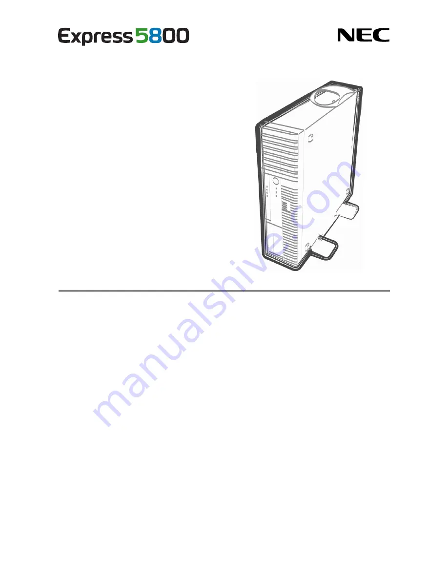
Express5800/GT110d-S, GT110d-S (2C/i3-2120)

EXP281A 
User’s Guide 

Model Number:  N8100-1739F/1740F/1741F/1742F 


Chapter 1  General Description 

Chapter 2  Preparations 

Chapter 3  Setup 
 
Chapter 4  Appendix 

Содержание Express5800/GT110d-S (2C/i3-2120) EXP281A

Страница 1: ...101 02 August 2011 Second Edition NEC Corporation 2011 Express5800 GT110d S GT110d S 2C i3 2120 EXP281A User s Guide Model Number N8100 1739F 1740F 1741F 1742F Chapter 1 General Description Chapter 2...

Страница 2: ...tions connection of peripheral devices and ideal location for this server Chapter 3 Setting Up Your Server System BIOS configurations and summary of EXPRESSBUILDER PDF Chapter 4 Appendix Specification...

Страница 3: ...atest editions 11 Precautions for Use Be Sure to Read 12 Safety precautions 12 Symbols used in this document and on warning labels 13 Safety notes 14 General 14 Power supply and power cord use 15 Inst...

Страница 4: ...1 1 Safety Precautions 44 1 2 Anti static Measures 45 1 3 Overview of Installation and Removal 46 1 4 Removing the Side Cover 47 1 5 Removing the Front Bezel 48 1 6 Internal Flash Memory 49 1 6 1 Inst...

Страница 5: ...an expansion 2 5 inch HDD cage 95 1 12 2 Installation 97 1 12 3 Removal 98 1 12 4 Removing the 2 5 inch HDD cage for additional drives 98 1 13 Optical Disk Drive 99 1 13 1 Replacing drives 99 1 13 2...

Страница 6: ...n On Screen Items and Key Usage 129 2 4 Cases that Require Configuration 131 3 EXPRESSSCOPE ENGINE 3 133 3 1 Overview 133 3 2 EXPRESSSCOPE ENGINE 3 Network configuration 133 4 EXPRESSBUILDER 135 4 1 F...

Страница 7: ...ccur Note Indicates items that must be confirmed when handling the server or operating software Tips Indicates information that is helpful to keep in mind when using this server Optical disk drives Th...

Страница 8: ...bit Editions unless otherwise stated The following appears on EXPRESSBUILDER screen Windows Server 2008 64 bit Edition Windows Server 2008 x64 Windows Server 2008 32 bit Edition Windows Server 2008 x3...

Страница 9: ...marks or trademarks of Adaptec Inc of the United States LSI and the LSI logo design are trademarks or registered trademarks of LSI Corporation Adobe the Adobe logo and Acrobat are trademarks of Adobe...

Страница 10: ...t This equipment generates uses and can radiate radio frequency energy and if not installed and used in accordance with the instruction manual may cause harmful interference to radio communications Op...

Страница 11: ...or omissions please contact your retailer 5 Regardless of these 4 items NEC Corporation assumes no responsibility for effects resulting from operations 6 The sample values used in this document are no...

Страница 12: ...ls WARNING or CAUTION is used to indicate a degree of danger These terms are defined as follows WARNING Indicates there is a risk of death or serious personal injury CAUTION Indicates there is a risk...

Страница 13: ...shock or fire may be caused Do not touch the server with wet hand Otherwise an electric shock may be caused Do not touch the component specified by this symbol Otherwise an electric shock or burn may...

Страница 14: ...esent If smoke odor or noise is present immediately turn off the server and disconnect the power plug from the outlet then contact the store where you purchased the product or your maintenance service...

Страница 15: ...If you want to use an AC cord set with a ground wire of class OI be sure to connect the ground wire before inserting the power plug into the outlet Before disconnecting the ground wire be sure to disc...

Страница 16: ...with staples or equivalents Do not pinch the power cord Keep chemicals away from the power cord Do not place any object on the power cord Do not alter modify or repair the power cord Do not use a dam...

Страница 17: ...cals that accelerate corrosion such as NaCl or sulfur or conductive materials Failure to follow this warning may cause the wiring on the printed wiring board to short circuit leading to fire If you ha...

Страница 18: ...move lithium NiMH or Li ion batteries The server contains the lithium NiMH or Li ion battery some optional devices have a lithium NiMH or Li ion battery installed Do not remove the battery Placing a b...

Страница 19: ...fall resulting in personal injury or property damage Do not place any object that weighs 5 kg or more on top of horizontally mounted servers The maximum weight that can be placed on top of the server...

Страница 20: ...ial hazards This label is either attached or printed on the component to draw attention from users to potential hazards involved in handling the server Do not remove or black out this label and keep i...

Страница 21: ...types of failure Refer to Chapter 1 Maintenance 2 Daily Maintenance in Maintenance Guide for details about cleaning Momentary voltage drop may occur due to lightning strike To prevent this use of UPS...

Страница 22: ...winter 10 C or more differences between the room temperature and atmospheric temperature Disk devices Approximately 2 to 3 hours Tape media Approximately 1 day For optional devices we recommend you u...

Страница 23: ...from reflecting bright lights and to make the display contents easy to see Working without adjusting the display to a comfortable angle makes it difficult for you to maintain a proper posture and you...

Страница 24: ...tures of this server and the name of each part 1 Introduction 2 Accessories Verify the condition of your server s accessories 3 Standard Features Check and maintain the server system by using the func...

Страница 25: ...on processor Intel Pentium processor Intel Core TM i3 processor NEC s latest technology and architectures realize high power and high speed operation that cannot be matched by existing servers The ser...

Страница 26: ...505 2 1 EXPRESSBUILDER 4 Getting Started Power cord x 1 1 Only for 3 5 inch disk models The number of the cable depends on the Hard Disk Drive configuration 2 Only for 2 5 inch disk models 3 If an in...

Страница 27: ...Array also available as an option BIOS password feature Management utilities NEC ESMPRO ExpressUpdate Remote controlling featuer EXPRESSSCOPE Engine 3 RAID System management utility Universal RAID Uti...

Страница 28: ...e AC Link feature Remote console feature Baseboard Management Controller BMC conforming to IPMI v2 0 Self diagnosis Power On Self Test POST Test and Diagnosis T D utility Easy setup EXPRESSBUILDER set...

Страница 29: ...re Monitors the temperature inside of the chassis Fan Monitors the fans Voltage Monitors the voltage inside of the chassis Power supply Monitors the power supply unit System environment Door Monitors...

Страница 30: ...Management By using NEC ESMPRO Manager and ExpressUpdate Agent you can manage firmware or software on the server and update them by applying an update package This function automatically updates mult...

Страница 31: ...ing accessed 5 Status LED green amber This LED indicates the server status It lights green when the server is operating normally 6 Front USB connectors These connectors are used to connect devices tha...

Страница 32: ...ghts green when the server is operating normally and lights or flashes amber when errors occur 6 Front USB connectors These connectors are used to connect devices that support the USB interface 7 Fron...

Страница 33: ...is server Use the switch only when there is something wrong with EXPRESSSCOPE Engine 3 BMC 8 USB connectors These connectors are used to connect devices that support the USB interface 9 LAN connectors...

Страница 34: ...General Description 4 3 Internal view 3 5 inch Hard Disk Drive model air cooled type 1 Power supply unit 2 CPU cooling fan 3 DIMM slots 4 3 5 inch Hard Disk Drive 5 Optical disk drive 6 3 5 inch devic...

Страница 35: ...Disk Drive model water cooled type 1 Power supply unit 2 Water cooling unit for cooling CPU 3 DIMM slots 4 3 5 inch Hard Disk Drive 5 Optical disk drive 6 3 5 inch device bay 7 Motherboard 8 Radiator...

Страница 36: ...Description 2 5 inch Hard Disk Drive model air cooled type 1 Power supply unit 2 CPU cooling fan 3 DIMM slot 4 SAS backplane 5 2 5 inch Hard Disk Drive 6 HDD fan 7 Optical disk drive 8 3 5 inch devic...

Страница 37: ...del water cooled type 1 Power supply unit 2 CPU cooling fan for cooling CPU 3 DIMM slot 4 SAS backplane 5 2 5 inch Hard Disk Drive 6 HDD fan 7 Optical disk drive 8 3 5 inch device bay 9 Motherboard 10...

Страница 38: ...COM B connector for N8117 01A 17 SPI Flash Mezzanine connector EXPRESSSCOPE profile key SPI flash memory has been installed where BIOS and BMC configuration data is stored Move it when replacing MB t...

Страница 39: ...n explains the indication and meanings of the server LEDs 3 5 inch Hard Disk Drive model 2 5 inch Hard Disk Drive model Front view Rear view Disk LED Power LED Disk access LED Optical disk LED Status...

Страница 40: ...graded state Flashing green An uncorrectable memory error has often occurred Identify the device in degraded state by using the BIOS setup utility SETUP and replace it as soon as possible The power is...

Страница 41: ...ve is being accessed If a 2 5 inch Hard Disk Drive model is used in RAID System by using an optional RAID Controller the LED lights amber and green alternately when the Hard Disk Drive failed and flas...

Страница 42: ...face is used The two LAN connectors for data transmission support 1000BASE T 100BASE TX and 10BASE T and the LED indicates which network interface is being used Amber Operating with 1000BASE T Green O...

Страница 43: ...This chapter describes preparations for using this server 1 Installing Internal Optional Devices You can skip this section if you did not purchase any optional devices 2 Ideal Location and Connection...

Страница 44: ...the warranty period 1 1 Safety Precautions Be sure to observe the following precautions to install and remove optional devices properly and safely WARNING Be sure to observe the following precautions...

Страница 45: ...periodically touching a metal surface while working on the components Select a suitable work space Work with the server on the anti static or concrete floor When you work with the server on a carpet...

Страница 46: ...pter 2 1 4 Removing the Side Cover 5 Remove the front bezel if applicable Refer to Chapter 2 1 5 Removing the Front Bezel 6 Depending on the components to be installed or removed follow the procedure...

Страница 47: ...ly and gently 4 Remove the side cover While pressing the two eject buttons slide the cover backward and lift it off Important BRACKET KEY This equipment is intended for installation in a location with...

Страница 48: ...arations 2 Release the three release tabs on the front bezel 1 in the direction of the arrow shown in the image and then pull the front bezel forward slightly until it comes off the frame 2 Important...

Страница 49: ...al Flash Memory 1 6 1 Installation Install the Internal Flash Memory in the following procedure 1 Refer to steps 1 to 5 in Chapter 2 1 3 Overview of Installation and Removal for preparations 2 Attach...

Страница 50: ...stalling a DIMM from a third party may cause the server to fail You will be charged to repair failures or damages caused by the use of such products even within the warranty period Read through Chapte...

Страница 51: ...Windows Server 2008 Enterprise x86 Edition 64 GB Windows Server 2008 Enterprise x64 Edition Windows Server 2008 R2 Enterprise 2 TB 32 GB RedHat Enterprise Linux 5 Server x86 16 GB 16 GB RedHat Enterpr...

Страница 52: ...nd keyslot preventing being wrongly inserted 5 Firmly close the lever 6 Continue to install or remove internal optional devices mount and connect the server and turn it on 7 Confirm that no error mess...

Страница 53: ...too much pressure on a DIMM or pulling a DIMM at an angle may break the DIMM or slot Gently pull it straight out of the slot 4 Assemble the server 5 Turn on the server and confirm that no error messa...

Страница 54: ...ated even with only one Physical Device Understand the characteristics of each RAID Controller such as available RAID levels or Hard Disk Drives and choose an appropriate RAID Controller Logical Drive...

Страница 55: ...oftware controlled RAID System Hard Disk Drive Jumper settings on the motherboard and backplane Change the jumper pin settings as described below Jumper pins on motherboard SWRAID Enabled 2 3 Disabled...

Страница 56: ...nterface cable supplied with the server For 3 5 inch Hard Disk Drives K410 253 00 internal SAS SATA cable For 2 5 inch Hard Disk Drives K410 180 00 internal SAS cable Jumper settings on the motherboar...

Страница 57: ...N8103 130 4 N8103 134 RAID 10 4 4 RAID 50 6 Use SAS SATA Hard Disk Drives or SSDs that have the same capacity and rotational speed As the size of Logical Drive cannot be specified in RAID 10 with the...

Страница 58: ...n OS system event log Models with 3 5 inch Hard Disk Drives installed Slot numbers indicated Insert position numbers displayed on the server On board RAID Controllers Optional RAID Controllers N8103 1...

Страница 59: ...ions The insert position number displayed on the server 1 0 0 1 2 Models with 2 5 inch Hard Disk Drives installed when expansion 2 5 inch HDD cages are installed 0 1 2 HDD cage 4 5 Models with 3 5 inc...

Страница 60: ...ty such as data or other devices might be destroyed Use the extra battery that supports the RAID Controller used The extra battery is a very delicate electronic device Before installation touch the me...

Страница 61: ...g to the user s guide for the extra battery Connecting the battery control cable Referring to the image below connect the battery control cable into the battery pack Check the orientation of the conne...

Страница 62: ...t Bezel remove the side cover and front bezel 3 If a RAID Controller is installed remove the center bar to disconnect the internal SAS cable and remove the RAID Controller For details refer to Chapter...

Страница 63: ...User s Guide 63 Chapter 2 Preparations Installing a battery pack to 2 5 inch Hard Disk Drive models 1 Remove the file device or blank panel For the blank panel pull it toward you while pressing the ta...

Страница 64: ...Chapter 2 Preparations 3 Engage the tabs of the bracket with the grille of the blank cover and fix it with the attached screw large Refer to the image below for the installation position Tab Engage th...

Страница 65: ...s5800 GT110d S User s Guide 65 Chapter 2 Preparations 4 Engage the tabs at the lower part of the blank cover with the chassis and fix it with the two screws If the cable is too long arrange it neatly...

Страница 66: ...g a battery pack to 3 5 inch Hard Disk Drive models 1 Remove one screw from the blank cover and slide it to the side to release the blank cover 2 Engage the tabs of the bracket with the grille of the...

Страница 67: ...onal Devices Express5800 GT110d S User s Guide 67 Chapter 2 Preparations 3 While pushing the blank cover to the right fix it with one screw If the cable is too long arrange it neatly such as by coilin...

Страница 68: ...tor of the battery control cable to the connector board on the RAID Controller Check the orientation of the connector and connect the cable straight into the connector Be careful not to press it in at...

Страница 69: ...5800 GT110d S User s Guide 69 Chapter 2 Preparations 2 Install a RAID Controller into the PCI slot and fix it in place Be careful not to disconnect any cables 3 Connect the internal SAS cable that you...

Страница 70: ...attery Installing the battery in the server This section describes how to install an extra battery in the server Note that the installation position and procedure differ for 2 5 inch Hard Disk Drive m...

Страница 71: ...rient the remote battery connection board so that it will fit the connector on the RAID Controller and fix it with three screws from the rear side 2 After connecting the connection board place and fix...

Страница 72: ...nto the battery pack Check the orientation of the connector and connect the cable straight into the connector Make sure the connector is oriented correctly by checking the following two points Importa...

Страница 73: ...inch Hard Disk Drive models 1 Remove the file device or blank panel For the blank panel pull it toward you while pressing the tab on the right 2 Remove the two screws from the blank cover 3 Pass the b...

Страница 74: ...Chapter 2 Preparations 4 Engage the tabs of the bracket with the grille of the blank cover and fix it with the attached screw large Refer to the image below for the installation position Tab Engage th...

Страница 75: ...of the blank cover with the chassis and fix it with the two screws If the cable is too long arrange it neatly such as by coiling it once within the chassis This concludes the installation of the batt...

Страница 76: ...to release the blank cover 2 Pass the bracket containing the battery and which is connected to the remote cable through the opening from which the blank cover was removed 3 Engage the tabs of the bra...

Страница 77: ...k cover to the right fix it with one screw If the cable is too long arrange it neatly such as by coiling once within the chassis This concludes the installation of the battery module in a 3 5 inch Har...

Страница 78: ...e where anti static measures have not been taken For an explanation of electrostatics refer to Chapter 2 1 2 Anti static Measures When installing PCI cards refer to Chapter 2 1 10 2 List of option dev...

Страница 79: ...ble below PCI device Bus number Device number Function number Onboard NIC1 4h 0 0 Onboard NIC2 4h 0 1 Slot 1 2h 0 Slot 2 3h 0 Slot 3 1h 0 Slot 4 6h 0 0 Set Disabled for the optional ROM of a LAN devic...

Страница 80: ...N8104 134 1000BASE T connection board 2 ch Card performance PCI EXPRESS x4 For adding LAN Teaming AFT SFT ALB and bonding with N8104 134 and on board LAN is supported Up to 2 teams per system Up to 2...

Страница 81: ...134 1000BASE T connection board 2 ch Card performance PCI EXPRESS x4 For adding LAN Teaming AFT SFT ALB and bonding with N8104 134 and on board LAN is supported Up to 2 teams per system Up to 2 ports...

Страница 82: ...connection board 2 ch Card performance PCI EXPRESS x4 For adding LAN Teaming AFT SFT ALB and bonding with N8104 134 and on board LAN is supported Up to 2 teams per system Up to 2 ports per team N8117...

Страница 83: ...n board 2 ch Card performance PCI EXPRESS x4 For adding LAN Teaming AFT SFT ALB and bonding with N8104 134 and on board LAN is supported Up to 2 teams per system Up to 2 ports per team Can be installe...

Страница 84: ...settings on the card are properly set according to the instruction manual supplied with the card if necessary 2 Refer to Chapter 2 1 3 Overview of Installation and Removal for preparations 3 Remove t...

Страница 85: ...rver 9 Turn on the server and confirm that no error messages are displayed in POST If an error message is displayed take notes on the message and ask your maintenance service company for maintenance 1...

Страница 86: ...move the side cover while referring to Chapter 2 1 4 Removing the Side Cover 3 Refer to installation step 4 to open the PCI slot retention 4 Remove the card 5 Attach the expansion slot cover and refer...

Страница 87: ...lled in water cooled models The component parts for N8117 01A are as follows Item no Item name Specification Amount Remarks 1 RS 232C connector kit manual 856 125671 002 1 2 RS 232C cable A 804 063264...

Страница 88: ...Chapter 2 Preparations 5 Remove the expansion slot cover aligned with the slot where you are going to install a card Important Keep the removed slot cover for future use 6 Make sure that you are prop...

Страница 89: ...lowing for the position of the COM connector for internal connections Important If connecting the cable fit it to the polarizing key of the connector and be careful not to connect it improperly The N8...

Страница 90: ...e installed in the 3 5 inch Hard Disk Drive model Important Use Hard Disk Drives specified by NEC Installing a third party Hard Disk Drive might cause a failure of the server and the Hard Disk Drive Y...

Страница 91: ...s Location of the bay where the drives will be installed Serial ATA connector of the connecting motherboard 1 Bottom Serial ATA connector 0 2 Top Serial ATA connector 1 2 Refer to Chapter 2 1 3 Overvi...

Страница 92: ...vided by this device screw set 505 of four screws to secure the Hard Disk Drive Using screws of a length greater than that required can cause damage to the Hard Disk Drive 10 Install the Hard Disk Dri...

Страница 93: ...s not yet completely erased can be recovered by using special software and reused by unauthorized parties To avoid such problems it is strongly recommended that you use commercial software or services...

Страница 94: ...Disk Drives in order from slot 0 and mount the SSDs to the remaining slots You can use a combination of an SAS Hard Disk Drive in the standard cage and an SATA Hard Disk Drive in the expansion cage I...

Страница 95: ...ives by using the following procedure 1 Refer to Chapter 2 1 3 Overview of Installation and Removal for preparations 2 Remove the side cover and front bezel while referring to Chapter 2 1 4 Removing t...

Страница 96: ...Connect the fan cable of the HDD cage to the motherboard For details refer to Chapter 2 1 15 Connecting cables 9 Push the HDD cage all the way into the server until it locks with a clicking sound 10 U...

Страница 97: ...ed when you hear a clicking sound Important Use Hard Disk Drives recommended by NEC For details consult with the store where you made your purchase or your maintenance service company Note Refer to th...

Страница 98: ...ems it is strongly recommended that you use commercial software or services to securely erase data For information on erasing data contact the store where you purchased the product or your maintenance...

Страница 99: ...ocument remove all Hard Disk Drives installed in the 2 5 inch HDD cage for additional drives 4 Referring to Chapter 2 1 12 1 Installing an expansion 2 5 inch HDD cage remove the HDD cage by reversing...

Страница 100: ...g to Chapter 2 1 4 Removing the Side Cover and 1 5 Removing the Front Bezel 3 While pressing the latch of the SATA cable disconnect the SATA cable from the optical disk drive 4 While pressing the stop...

Страница 101: ...ots for the installation of backup devices such as optical disk drives and magnetic tape drives As a standard there is one expansion slot Tips Controller board options and internal cables might be req...

Страница 102: ...t the termination resistance of the device to OFF Important If a SCSI device is installed specify an SCSI ID that is not already used by another external SCSI device that is connected to the same cont...

Страница 103: ...device all the way until it locks with a clicking sound 10 Assemble the server 11 For SCSI devices use the BIOS utility of the SCSI controller and specify the transfer rate and other settings For more...

Страница 104: ...isk Drive models When adding Hard Disk Drives connect the cables as in the following figure Install the Hard Disk Drives in order from the bottom Connect the first Hard Disk Drive to SATA0 the second...

Страница 105: ...e K410 253 00 for use with RAID Controllers Install the Hard Disk Drives in order from the bottom RAID Controller N8103 128 129 130 134 Motherboard Power supply unit Second Hard Disk Drive First Hard...

Страница 106: ...ected to a RAID Controller To display this status connect the LED cable provided with the optional K cord cable K410 253 00 Connect the LED connector on the motherboard to the connector on the RAID Co...

Страница 107: ...129 130 134 the dedicated cable K410 180 00 is required Install Hard Disk Drives from Slot 0 in ascending order Power supply unit Motherboard Extra battery N8103 121 141 Optical disk drive Slot 0 Firs...

Страница 108: ...SATA connector of the cable with the SATA connector number on the motherboard Also connect the cable to the SGPIO connector on the motherboard Install Hard Disk Drives from Slot 0 in ascending order P...

Страница 109: ...ached to the 2 5 inch expansion HDD cage Slot 1 Second Hard Disk Drive Optical disk drive Power supply unit Motherboard Internal SATA cable K410 180 00 Battery cable attached to the expansion battery...

Страница 110: ...ID for another SCSI device Because a connector for terminating SCSI connections is installed in SCSI cable K410 181 00 specify the termination settings of the 3 5 inch device to Disabled b If mountin...

Страница 111: ...S User s Guide 111 Chapter 2 Preparations c If using the front USB connector when mounting the internal USB device Use internal USB cable K410 245 00 to connect the device Motherboard USB device USB c...

Страница 112: ...ting the power cables Power cables other than those shown here are not used by the devices 1 For 3 5 inch Hard Disk Drive models 2 For 2 5 inch Hard Disk Drive models P3 P4 P1 P10 P11 P2 P5 Optional d...

Страница 113: ...ions 1 16 Attaching the Front Bezel You can attach the front bezel by reversing the removal procedure Insert the three tabs on the lower part of the front bezel into the holes on the front of the serv...

Страница 114: ...ed in the holes on the server frame Also make sure that the hooks at the front of the cover are engaged with the server frame when sliding the side cover forward to attach If they are not engaged with...

Страница 115: ...duct Install and store only in the specified environment The environment suitable for the server is as follows Hold the server firmly and slowly and gently place it in the position in which it is to...

Страница 116: ...ion is connected Place where intense vibration may be generated Place where some objects may be fallen Place near a device generating intense magnetic field such as TVs radios broadcast communication...

Страница 117: ...ientation as instructed below Also be sure to attach the air duct for cooling on the top of the server a Removing installing the stabilizer Removing the stabilizer Release the lock plate and slide it...

Страница 118: ...up the server as shown in the image b Installing the air duct Important To maintain the cooling effect in the server be sure to attach the air duct Do not install the server in an area where the vent...

Страница 119: ...ct on the right side of the server the server top if vertically mounted Important If the server is horizontally mounted you may put devices that weigh less than 5 kg on the top of the server To mainta...

Страница 120: ...llowing precautions to use the server safety Failure to observe the precautions may cause death or serious injury For details refer to Safety precautions in Precautions for Use Do not hold the power p...

Страница 121: ...server beforehand Some devices from a third party cannot be used with the server You cannot connect directly to the dedicated line through the serial port that is equipped with the server as standard...

Страница 122: ...s Guide 122 Chapter 2 Preparations Display unit Front view Rear view USB devices such as a FD drive A device with serial interface such as a modem USB devices such as a terminal adapter Finally conne...

Страница 123: ...e outlet provided at the rear of the UPS For details refer to the instruction manual supplied with the UPS In order to link the power supply from the UPS with the power on off of this server the BIOS...

Страница 124: ...tings by following the instructions in this section 3 EXPRESSSCOPE Engine 3 EXPRESSSCOPE Engine 3 provides useful features through the Baseboard Management Controller BMC 4 EXPRESSBUILDER EXPRESSBUILD...

Страница 125: ...eral devices that connect to the display monitor and the server Note If the power cord is connected to power control system such as an Uninterruptible Power Supply UPS make sure that the power control...

Страница 126: ...he manual that comes with the optional board before any key entry Powering on the server after you installed or removed an optional PCI board or moved it to another slot may display the message that i...

Страница 127: ...d Drive 5 If a controller which has its dedicated BIOS such as a SCSI controller board is installed a message that prompts you to start the dedicated utility to set each board is displayed Example SCS...

Страница 128: ...an error it displays an error message on the screen or beeps for some errors For descriptions of error messages causes and countermeasures refer to Maintenance Guide Important Take notes on the messag...

Страница 129: ...boot In most of cases the SETUP was configured for optimal performance before the server was shipped to you Therefore in most of cases you should not need to use the SETUP utility Use only when the ca...

Страница 130: ...the selected item You cannot use this key when a menu which has on the left is selected Enter key Press this key to confirm the selected parameter Esc key Pressing this key takes you to the previous...

Страница 131: ...F3 key If you press this key the following window appears If you select Yes restore the parameters of the currently selected item to the default setting This might be different from the parameters con...

Страница 132: ...Slot n Option ROM Enabled n is PCI slot number of the RAID Controller Change the boot order of devices Boot Boot Option Priorities Change the boot priority Use remote power on function from modem Adv...

Страница 133: ...password 3 times operation stops You cannot operate further Turn off the power Saving changes If you finish configuration select Save Exit and then Save Changes and Exit to save changes and exit If y...

Страница 134: ...se for remote management N8115 04 is required 3 2 EXPRESSSCOPE ENGINE 3 Network configuration To enable EXPRESSSCOPE Engine 3 to be used via network network configuration is required The following pro...

Страница 135: ...ty 5 If Property is selected the following screen is displayed On this screen specify whether to use DHCP and if DHCP is not used configure IP Address Subnet Mask 6 Connect the LAN cable to the manage...

Страница 136: ...C ESMPRO Agent Maintenance Diagnoses your server system To use this feature select Tool menu in the menu after boot Storage of documents Stores various documents including User s Guide Installation Gu...

Страница 137: ...ftware Components Express5800 GT110d S User s Guide 137 Chapter 3 Setup 5 Installing Software Components Continue to install software components such as OS Refer to the instructions below Installation...

Страница 138: ...ocedure If the power cord of the server is connected to a UPS refer to the documentation supplied with the UPS or the documentation for the application controlling the UPS 1 Shut down the OS 2 If the...

Страница 139: ...Express5800 GT110d S User s Guide 139 NEC Express5800 Series Express5800 GT110d S Appendix 1 Specifications 2 Interrupt Lines...

Страница 140: ...CI EXPRESS 1 slot x8 x8 socket PCI EXPRESS 2 slot x4 x8 socket 32 bit 33 MHzx1 slot USB Front 2 ports rear 4 ports internal 2 ports version 2 0 compatible Serial 1 port D sub 9 pin 2 Network 2 ports 1...

Страница 141: ...socket USB Front 2 ports rear 4 ports internal 2 ports version 2 0 compatible Serial 1 port D sub 9 pin 2 Network 2 ports 100Base T 100Base TS 10Base T RJ 45 Management LAN port RJ 45 External interfa...

Страница 142: ...you add optional devices Interrupt lines As factory settings interrupt lines are assigned as follows IRQ Peripheral Device Controller IRQ Peripheral Device Controller 0 System timer 8 Real time clock...

Отзывы: