background image

1. Installing Internal Optional Devices 


Express5800/D120h  User’s Guide 

76 

Chapter 2  Preparations 

1.10


Hard Disk Drive 

Bays for installing hard disk drives are provided at the front of the server. 

A hard disk drive mounted in a dedicated drive tray can be purchased. Install the hard disk drive on the server 
with it mounted in the drive tray. 


Important  Use hard disk drives specified by NEC. Installing a third-party hard disk drive 

might cause a failure of the server as well as the hard disk drive. 


Note the following precautions to install hard disk drives. 

  Hard disk drives having different capacities, types, or rotational speeds cannot be installed together. 

  In the RAID System, all the hard disk drives in a group (pack) must have the same capacity, interface type, 

and rotational speed.   

  If using hard disk drives in a RAID System, jumper settings or a change of cables may be required. 


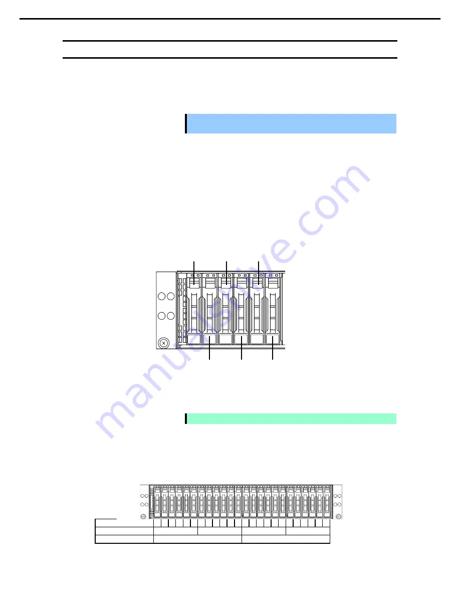
The expansion bay of the 1U server module has six slots so that up to six hard disk drives can be installed to it. 

Unique slot numbers have been assigned to each slot.   


The expansion bay of the 2U server module has twelve slots so that up to twelve hard disk drives can be 
installed to it. Unique slot numbers have been assigned to each slot. 


Note 

Hard disk drive number depends on your OS. 


The correspondence between the position of the expansion bay and the slot to implement the server module is 
shown below.   
Mount the hard disk drive from the left (from the smaller slot number) in the expansion bay corresponding to 
each server module. 


Expansion Bay Slot Number  1  2  3  4  5  6  7  8  9  10  11  12  13  14  15  16  17  18  19  20  21  22  23  24 

1U server module 

Slot 1 

Slot 2 

Slot 3 

Slot 4 

2U server module 

Slot 2 

Slot 4 

Slot 2 

Slot 1 

Slot 3 

Slot 5 

Slot 4 

Slot 6 

Содержание EXP710

Страница 1: ...rver Express5800 Series Express5800 D120h EXP710 EXP711 EXP712 User s Guide Chapter 1 General Description Chapter 2 Preparations Chapter 3 Setup Chapter 4 Appendix 10 117 01 101 02 November 2017 NEC Corporation 2017 ...

Страница 2: ...nnection of peripheral devices and suitable location for this server Chapter 3 Setup System BIOS configurations and summary of EXPRESSBUILDER Chapter 4 Appendix Specifications and other information Installation Guide Windows Chapter 1 Installing Windows Installation of Windows and drivers and precautions for installation Chapter 2 Installing Bundled Software Installation of NEC ESMPRO Universal RA...

Страница 3: ...s 14 Chapter 1 General Description 16 1 Introduction 17 2 Accessories 18 3 Features 19 4 Names and Functions of Parts 22 4 1 Front View 22 4 2 Rear View 23 4 3 External View 25 4 4 Internal View 26 4 5 Motherboard 28 4 6 Status Indicators 29 4 6 1 POWER LED 29 4 6 2 STATUS LED CMC STATUS LED 29 4 6 3 UID LED 30 4 6 4 LED on a hard disk drive 32 4 6 5 LEDs for LAN connectors 33 4 6 6 AC POWER LED o...

Страница 4: ...3 Cold Redundant Feature 83 Replacing a failing power supply unit 83 1 13 TPM kit N8115 31 85 Installation 85 1 14 Additional RS 232C connector N8117 01A 86 Installation 86 2 Installation and Connection 87 2 1 Installation 87 Installing Rack 87 Installing the server to the rack or removing it from the rack 89 Installation Removal of server module 94 Installation of blank module N8141 85F 96 2 2 Co...

Страница 5: ...Contents Express5800 D120h User s Guide 5 6 Turning Off the Server 116 Chapter 4 Appendix 117 1 Specifications 118 1 1 Server Module 118 1 2 Module Enclosure 121 2 Glossary 122 3 Revision Record 123 ...

Страница 6: ...cates the presence of a hazard if the instruction is ignored An image in the symbol illustrates the hazard type Prohibited Action This symbol indicates prohibited actions An image in the symbol illustrates a particular prohibited action Mandatory Action This symbol indicates mandatory actions An image in the symbol illustrates a mandatory action to avoid a particular hazard Example in this guide W...

Страница 7: ...res described are not followed server failure data loss and other serious malfunctions could occur Note Indicates items that must be confirmed when handling hardware or operating software Tips Indicates information that is helpful to keep in mind when using this server Hard disk drive Unless otherwise stated hard disk drive described in this document refer to both of the following Hard disk drive ...

Страница 8: ...ows Server 2016 Windows Server 2016 Standard Windows Server 2016 Datacenter Windows Server 2012 R2 Widnows Server 2012 R2 Standard Widnows Server 2012 R2 Datacenter Abbreviation of Power On Self Test POST means the following feature in this manual Power On Self Test Abbreviation of Baseboard Management Controller BMC means the following feature in this manual Baseboard Management Controller Abbrev...

Страница 9: ...ountries Intel Pentium and Xeon are registered trademarks of Intel Corporation of the United States QLogic is a registered trademark of Qlogic Corporation Broadcom NetXtreme LiveLink Smart Load Balancing are registered trademarks or trademarks of the Broadcom Corporation in the U S and other countries All other product brand or trade names used in this publication are the trademarks or registered ...

Страница 10: ...OF SUCH DAMAGE Copyright c 2004 2007 Intel Corporation All rights reserved This program and the accompanying materials are licensed and made available under the terms and conditions of the BSD License which accompanies this distribution The full text of the license may be found at http opensource org licenses bsd license php THE PROGRAM IS DISTRIBUTED UNDER THE BSD LICENSE ON AN AS IS BASIS WITHOU...

Страница 11: ...e may be distributed used and modified under the terms of BSD license Redistribution and use in source and binary forms with or without modification are permitted provided that the following conditions are met 1 Redistributions of source code must retain the above copyright notice this list of conditions and the following disclaimer 2 Redistributions in binary form must reproduce the above copyrig...

Страница 12: ...4 NEC Corporation assumes no responsibility for effects resulting from your operations 6 The sample values used in this document are not actual values Keep this document for future reference Latest editions This document was created based on the information available at the time of its creation The screen images messages and procedures are subject to change without notice Substitute as appropriate...

Страница 13: ... are attached on or near the components with potential hazards This label is either attached or printed on the component Do not remove or black out this label and keep it clean If no label is attached or printed on the server or if there is a label coming off or stained contact your sales representative ...

Страница 14: ...clean the server to prevent various types of failure For details see Chapter 1 Maintenance 2 Daily Maintenance in Maintenance Guide Momentary voltage drop may occur due to lightning strike To prevent this use of UPS is recommended We do not support that any copy protected CD that does not conform to standards will play on the server s optical disk drive In the following cases check and adjust the ...

Страница 15: ...n from reflecting bright lights and to make the display contents easy to see Working without adjusting the display to a comfortable angle makes it difficult for you to maintain a proper posture and you will get tired easily Adjust the viewing angle before use Adjust the brightness and contrast of the display Display screens have functions to control brightness and contrast The most suitable bright...

Страница 16: ...hapter introduces the features of this server and the name of each part 1 Introduction 2 Accessories Describes the accessories of the server 3 Features Describes the features of the server and server management 4 Names and Functions of Parts Describes the name of each part contained in this server 1 1 ...

Страница 17: ...rocessor NEC s latest technology and architectures realize high power and high speed operation that cannot be matched by existing servers The server is designed with consideration of not only reliability but also expandability which enables you to use it as a network server Read this document before using the server thoroughly to fully understand handling of Express5800 Series Server and appreciat...

Страница 18: ...and Regulatory Notices Getting Started Make sure you have all accessories and inspect them If an accessory is missing or damaged contact your sales representative Important The chassis serial number plate and maintenance label is located on the server If the serial number does not match the number on the warranty you may not be guaranteed against failure even within the warranty period Contact you...

Страница 19: ...lver 4116 processor 2 10GHz 12Core N8101 1098 Intel Xeon processor Gold 5118 processor 2 30GHz 12Core N8101 1367 Intel Xeon processor Gold 5120 processor 2 20GHz 14Core N8101 1368 Intel Xeon processor Gold 5122 processor 3 60GHz 4Core N8101 1069 Intel Xeon processor Gold 6130 processor 2 10GHz 16Core N8101 1370 Intel Xeon processor Gold 6132 processor 2 60GHz 14Core N8101 1371 Intel Xeon processor...

Страница 20: ...Redundant cooling fan Internal voltage monitoring feature Power redundant feature hot swapping supported Power supply throttle ring feature RAID Disk Array optional disk array controller is required Auto rebuild feature hot swapping supported BIOS password feature HDD hot swapping supported Management Utilities NEC ESMPRO System BIOS and firmware management feature ExpressUpdate Remote controlling...

Страница 21: ... a hard disk drive and additional power supply unit hot swap supported Slide rails for each installation Many built in Features Redundant power supply system supported El Torito Bootable CD ROM no emulation mode format supported Software power off Remote power on feature AC Link feature Remote console feature Baseboard Management Controller BMC conforming to IPMI v2 0 Chassis Management Controller...

Страница 22: ... drives 4 Pull out Tag A tag for showing the model number and serial number of the server 5 Unit ID UID Switch LED A switch for turning on off UID LED Pressing the switch once turns on UID LED and pressing again turns off the LED Commands from the software also cause it to turn on or blink 6 POWER Switch LED A switch for turning on off the server Press once to turn on the server POWER LED lights w...

Страница 23: ... number indicates the LAN connector 1 while 2 indicates the LAN connector 2 When Shared BMC LAN feature is enabled by the BIOS setting the LAN connector 1 can be shared as the LAN only for the management However this feature is not recommended considering the performance and security since the data for both connectors may be sent or received 11 Management LAN Connector A LAN connector which suppor...

Страница 24: ...4 Names and Functions of Parts Express5800 D120h User s Guide 24 Chapter 1 General Description 1 Slot 4 for GPGPU A slot for installing GPGPU 1 2U Server module ...

Страница 25: ...4 Names and Functions of Parts Express5800 D120h User s Guide 25 Chapter 1 General Description 4 3 External View ...

Страница 26: ...pter 1 General Description 4 4 Internal View 1U Server Module 1 Processor CPU 1 1 CPU 0 1 2 CPU 1 2 DIMM Option 3 Motherboard 4 Riser Card 4 1 Riser card Slot 1 4 2 Riser card Slot 2 5 Slot 3 only for Connection card Slot only for the LAN mezzanine 3 2 1 2 1 1 4 1 5 4 2 ...

Страница 27: ... of Parts Express5800 D120h User s Guide 27 Chapter 1 General Description 2U Server Module Top module Bottom module The same module as 1U server module as shown on the previous page 1 Riser Card Slot 4 Slot only for GPGPU 1 ...

Страница 28: ... Lithium Battery 5 PCI Riser Card Connector 1 for low profile card Slot 1 6 PCI Riser Card Connector 2 for low profile card Slot 2 7 Connection card Connector 3 only for the LAN mezzanine Slot 3 8 Clear NVRAM Jumper Switch 9 Clear Password Jumper Switch 10 Connector for TPM kits 11 Connector for ESXi base kits 12 SATA Connector 13 Connector for the optional COM only when using N8117 01A 14 Connect...

Страница 29: ... LED CMC STATUS LED While hardware is operating normally STATUS LED for the server module STATUS LED for enclosure light green If neither the STATUS LED nor STATUS LED for the server module STATUS LED for enclosure is ON in green or OFF this indicates an abnormality in this product Tips If you have installed NEC ESMPRO you can view error logs to check the causes of failures If the LED indication d...

Страница 30: ...fan unit is properly connected A voltage warning was detected Contact your sales representative One or more hard disk drives are failed Event log status 75 Check the system event log and it is not abnormal if the number of registrations is 75 It is recommended to clear the log by saving the log once CMC STATUS LED pattern Description Action On green The server is working normally Off The power of ...

Страница 31: ...used to identify the target server for maintaining among several servers installed in a rack Especially if this LED remains ON you can perform the maintenance work from the rear side of the rack without missing the target device UID LED pattern Description On blue The UID switch is pressed Off The UID switch is not pressed Tips UID LED can turn on and off by remote management software The UID swit...

Страница 32: ...on DISK LED 1 DISK LED 2 Blinking green On green Hard disk drive is being accessed Blinking amber RAID system only On green Hard disk drive is failing Contact your sales representative Blinking in green and umber alternately RAID system only On green Rebuilding is in progress When the failed hard disk drive is replaced rebuilding process starts automatically auto rebuilding feature Off On green It...

Страница 33: ...EED LED M CMC 1 2 This LED indicates which network interface is used LAN ports support 10GBASE T 1000BASE T 100BASE TX and 10BASE T Management LAN port supports 1000BASE T 100BASE TX and 10BASE T M CMC SPEED LED pattern Description On amber The port is operating with 10GBASE T interface On green The port is operating with 1000BASE T interface Off The port is operating with 100BASE TX or 10BASE T i...

Страница 34: ...server is powered on Blinking green The power cable is connected and AC power is supplied Cold Redundant feature is enabled On amber The power cord is not connected in redundant power configuration Connect the power cord Power unit is failing Contact your sales representative Blinking amber Power unit is failing Contact your sales representative Off The power is not supplied to the server Connect ...

Страница 35: ...ns This chapter describes preparations for using this server 1 Installing Internal Optional Devices You can skip this section if you did not purchase any optional devices 2 Installation and Connection Place the server in a suitable location and connect cables following this section 2 2 ...

Страница 36: ...safely WARNING Be sure to observe the following precautions to use the server safety Failure to observe the precautions may cause death or serious injury For details see Safety Precautions and Regulatory Notices Do not disassemble repair or modify the server Do not remove the lithium battery NiMH battery or Li ion battery Disconnect the power plug when installing and removing devices CAUTION Be su...

Страница 37: ...the server See Chapter 3 6 Turning Off the Server When adding hard disk drives only go to step 6 When adding power supply unit only go to step 7 When installing or removing other internal optional devices remove the server module from the module enclosure and put it on a flat rigid desk See Chapter 2 2 1 Installation If you remove the server module from module enclosure wait at least 30 seconds be...

Страница 38: ... When the server is working be sure to identify the target server by using UID Switch first before you turn off the server or disconnect a cable from the server The front and the rear UID LEDs work together To turn UID LED on press UID Switch When it is pressed again the LED will be off When the 1U server module is installed When the 2U server module is installed UID switch LED UID LED UID LED ...

Страница 39: ...or heat sink CPU H S PCI card LAN mezzanine card RAID controller SATA DOM VMware ESXi base kit TPM kit See steps 1 to 3 in Chapter 2 1 2 Overview of Installation and Removal for preparations Pull out the handle toward you while rotating the locking mechanism counterclockwise Hold the handle and pull out the server module horizontally Important If you remove the server module from the enclosure wai...

Страница 40: ...mber of processor cores supported by this server The maximum number of processor cores logical processors available on the server depends on the architecture x86 architecture and OS specs Maximum number of processor cores OS The maximum number of logical processors supported by OS The maximum number of logical processors supported by this server Microsoft Windows Server 2012 R2 Standard Microsoft ...

Страница 41: ...er for future use Important Do not touch the socket contacts Install the CPU to be added obliquely to the CPU clip plastic package and fix it gently and carefully Note Align the triangular marks Important Be sure to hold the CPU only at the edges Pay attention not to touch the bottom of the CPU Note Insert the CPU while aligning the notch on the CPU with the key on the CPU socket Bring down the CP...

Страница 42: ...hown as 1 and the Air Flow label on the Heat sink can be seen as position 2 5 Install CPU H S with COU installed to MB Important Before install heat sink onto MB please make sure to take the following steps Step 1 server front panel is on your left and rear is on your right Step 2 adjust the heat sink position to make Air Flow label can be seen on the top right corner which is shown in the instruc...

Страница 43: ... or remove internal optional devices mount and connect the server and turn it on 7 Run BIOS Setup Utility SETUP to confirm the following settings See Chapter 2 1 System BIOS in Maintenance Guide Chipset Processor Configuration Processor ID L2 Cache RAM L3 Cache RAM 8 After checking perform rebooting with Save Changes and Reset Replacement Removal To remove CPU reverse the installation procedure Af...

Страница 44: ...onfiguration up to 2 TB 128 GB x 16 can be installed on each server module In 1 CPU configuration up to 1 TB 128 GB x 8 can be installed on each server module Maximum supported memory size The maximum available memory size on the server depends on the OS architecture and specifications Maximum memory sizes OS The maximum memory size supported on each OS The maximum memory size supported on the ser...

Страница 45: ...4116 Gold 5118 Gold 5120 embedded model Model number and product name Memory clock speed Memory Voltage 1 2 V Number of memory boards per memory channel 1 2 N8102 703F 8GB additional memory board 1x8GB R 2400MHz N8102 704F 16GB additional memory board 1x16GB R N8102 705F 32GB additional memory board 1x32GB R N8102 706F 64GB additional memory board 1x64GB TSV R N8102 707F 128GB additional memory bo...

Страница 46: ...led See the table below to find allowable combination of DIMMs and install DIMMs starting from the largest capacity and from the smallest slot number Mixed combination of the DIMM that can be installed is not enabled Before adding DIMM refer to the combination list below to check whether the mixed combination is allowed or not Model number N8102 703 704 705 706 707 N8102 703 8GB 1x8GB R N8102 704 ...

Страница 47: ... DIMM_P1_J0 DIMM_P1_J1 DIMM_P1_G1 DIMM_P1_G0 DIMM_P1_H0 DIMM_P1_I0 DIMM slot number from top DIMM_P0_F0 DIMM_P0_E0 DIMM_P0_D0 DIMM_P0_D1 DIMM_P0_A1 DIMM_P0_A0 DIMM_P0_B0 DIMM_P0_C0 Motherboard CPU0 CPU1 6 5 4 8 7 1 2 3 The order of installing DIMMs 1CPU configuration The order of installing DIMMs 2CPU configuration 11 9 7 15 13 1 3 5 12 10 8 16 14 2 4 6 ...

Страница 48: ...from top DIMM_P1_L0 DIMM_P1_K0 DIMM_P1_J0 DIMM_P1_J1 DIMM_P1_G1 DIMM_P1_G0 DIMM_P1_H0 DIMM_P1_I0 DIMM slot number from top DIMM_P0_F0 DIMM_P0_E0 DIMM_P0_D0 DIMM_P0_D1 DIMM_P0_A1 DIMM_P0_A0 DIMM_P0_B0 DIMM_P0_C0 Motherboard CPU0 CPU1 4 3 1 2 Not installed The order of installing DIMMs 1CPU configuration The order of installing DIMMs 2CPU configuration 7 5 1 3 Not installed 8 6 2 4 Not installed ...

Страница 49: ...ry Configuration Memory Topology submenu Make sure the capacity of added DIMM is displayed properly See Chapter 2 1 System BIOS in Maintenance Guide 6 Select Chipset Runtime Error Logging Memory Error Enabling Clear Error Memory Even log on SMB and set Enable After changing perform rebooting with Save Changes and Reset Removal Replacement To remove DIMM reverse the installation procedure Note When...

Страница 50: ...erted is secured on the mother board Installing LAN Mezzanine Follow the steps below to install a LAN mezzanine Important To avoid static electricity see Chapter 1 1 8 Anti static Measures in Safety Precautions and Regulatory Notices 1 See steps 1 and 2 in Chapter 2 1 4 Removing Server Module for preparations 2 Remove the bracket on server module by removing three screws 3 Align the LAN mezzanine ...

Страница 51: ...itional riser card with the slots on the mother board and securely insert it 5 Fix it with three screws that were removed in step 2 6 Insert the server module to the original position in the enclosure Removing LAN Mezzanine For removing the LAN mezzanine reverse the installation procedure 1 Attach the bracket 2 Fix a screw ...

Страница 52: ... At this time take extreme care not to allow a flat blade screwdriver to damage the LAN connector or other boards If the device PCI board or USB device that can be booted is added or the Boot Mode is changed the boot priority may change Check the boot device priority in BIOS setup Boot USB CD DVD Check the display Boot USB Key Check the display Boot USB Hard Disk Check the display Boot Hard Disk C...

Страница 53: ...edicated to connect with internal hard disk drive N8103 184 SAS Controller Card performance PCI Express 3 0 x8 1 2 For connecting with external devices N8190 157A Fibre Channel Controller 16Gbps Optical Card performance PCI Express3 0 x8 1 2 For connecting with external Fibre Channel devices N8190 158A Fibre Channel Controller 2ch 16Gbps Optical Card performance PCI Express3 0 x8 1 2 For connectin...

Страница 54: ...module N8104 129 if needed N8117 01A Expansion RS 232C connector kit 3 1 For additional serial port RS 232C Cannot be installed 1 Data transfer rate of PCI slot Transfer bandwidth x Number of lanes Example x8 lane 64 Gbps uni directional 2 Indicates connector size A card up to the number of sockets can be connected Example x4 socket can connect with x1 and x4 cards but not x8 card 3 Use the cable ...

Страница 55: ...ress 3 0 x8 1 2 For connecting with external devices N8190 157A Fibre Channel Controller 16Gbps Optical Card performance PCI Express3 0 x8 1 2 For connecting with external Fibre Channel devices N8190 158A Fibre Channel Controller 2ch 16Gbps Optical Card performance PCI Express3 0 x8 1 2 For connecting with external Fibre Channel devices N8190 161 Fibre Channel Controller 16Gbps Optical カード性能 PCI E...

Страница 56: ...1 Graphics Card Cannot be installed 1 Data transfer rate of PCI slot Transfer bandwidth x Number of lanes Example x8 lane 64 Gbps uni directional 2 Indicates connector size A card up to the number of sockets can be connected Example x4 socket can connect with x1 and x4 cards but not x8 card 3 Use the cable RS 232C A 804 063264 020 4 Contact your service representative How to read the table The car...

Страница 57: ... Chapter 3 2 4 Cases That Require Configuration to select a boot mode to fit your environment Check the following BIOS settings when you have the RAID controller implemented Advanced PCI Subsystem Settings submenu PCI Express Slot x 2 Enable To connect a RAID controller optional SAS SATA cable K410 356 or K410 357 is required 1U server module The built in SAS SATA cable K410 356 is required See st...

Страница 58: ... to install a card see the table on Chapter 2 1 8 2 Supported cards and available slots Mount a PCI card RAID controller to the PCI 1 riser card Insert the PCI card RAID controller to PCI 2 riser card while aligning the terminal of the PCI card with the PCI 2 riser card slot At this time secure the bracket that was removed in step 4 with the screws that were removed in step 3 Screw ...

Страница 59: ...part of the PCI card may be too large to fit in the connector If you have trouble installing the board remove the board once and try again If you apply excessive pressure on the board a PCI card or riser card might break Connect the internal SAS SATA cable K410 356 to PORT 0 3 connector and PORT 4 7 connector on RAID controller Caution Align the label of the cable with the connector as described b...

Страница 60: ...Optional Devices Express5800 D120h User s Guide 60 Chapter 2 Preparations Fix the bracket with two screws removed in step 4 Mount the PCI 1 riser card removed in step 2 Fix the riser card with three screws removed in step 2 ...

Страница 61: ...ase keep the removed cable at your hand Connect the built in SAS SATA cable K410 356 to this connector Connect the cable also to the SGPIO connector adjacent to this connector in the same manner SGPIO connector cable label Front SGPA SGPA Rear SGPB SGPB Pass the built in SAS SATA cable K410 356 under the banding band and fix it For route of the built in SAS SATA cable K410 356 refer to the followi...

Страница 62: ...d to the default setting In that case configure the boot priority in Boot menu of BIOS Setup Utility For details see Chapter 3 2 BIOS Setup Utility SETUP 2U server module Built inSAS SATA cable K410 356 are required Built in SAS SATA cable K410 357 for 2Userver module have 2 types of cables in different length To remove the top and bottom of the modules see How to remove and install the top and bo...

Страница 63: ...d available slots Mount a PCI card RAID controller to the PCI 1 riser card Insert the PCI card RAID controller to PCI 2 riser card while aligning the terminal of the PCI card with the PCI 2 riser card slot At this time secure the bracket that was removed in step 4 with the screws that were removed in step 3 Align the pins of the PCI riser card with the slots on the mother board and securely insert...

Страница 64: ...f PCI cards the terminal part of the PCI card may be too large to fit in the connector If you have trouble installing the board remove the board once and try again If you apply excessive pressure on the board a PCI card or riser card might break Connect the internal SAS SATA cable K410 356 to PORT 0 3 connector and PORT 4 7 connector on RAID controller Caution Align the label of the cable with the...

Страница 65: ...hree screws removed in step 2 Raise up the banding band that fixes the original built in SAS SATA cable and then pull out the cable Return the banding band and fix it Pull out the cable and remove it while pressing the lock of the original built in SAS SATA cable Then the original built in SAS SATA cable can be removed Please keep the removed cable at your hand Lock ...

Страница 66: ...s Guide 66 Chapter 2 Preparations Connect the built in SAS SATA cable that was connected in step 10 to the expansion board via the upper server module In this case use the longer cable of the built in SAS SATA cable K410 367 Lower server module Upper server module ...

Страница 67: ... the shorter cable of the built in SAS SATA cable K410 367 Caution When connecting the cable it may touch the riser board Refer to the caution on the cable route in this section Upper server module Lower server module For route of the built in SAS SATA cable K410 357 refer to the following figure Although the following figure shows installation of N8103 176 177 178 the cable route when N8103 188 i...

Страница 68: ...d to set up the board For details refer to the manual that comes with the card If a PCI card including RAID Controller and LAN adapter which connects to any bootable device is added the boot priority might be changed to the default setting In that case configure the boot priority in Boot menu of BIOS Setup Utility For details see Chapter 3 2 BIOS Setup Utility SETUP a How to remove and install the...

Страница 69: ...e 69 Chapter 2 Preparations b Cautions of cable route To remove the PCI riser card of the slot PCI Slot 4 only for GPGPU remove the screws from six locations shown below Remove PCI raiser card on the slot for GPGPU PCI Slot 4 PCI raiser card on slot for GPGPU PCI Slot 4 ...

Страница 70: ...CI riser card Note Check the type of the card low profile supported by the PCI riser card and the type of the PCI card to be installed See steps 1 and 2 in Chapter 2 1 4 Removing Server Module for preparation To install the PCI board to PCI 1 remove the three screws securing the PCI 1 riser card Hold the both ends of the riser card and lift it straight to remove it To install the PCI board to PCI ...

Страница 71: ...3 176 177 178 188 and internal SAS SATA cable K410 356 K410 357 Important Do not touch the terminal part of riser cards or PCI cards and the signal pins of electric parts installed on the board Installing boards with dirt or oil can cause malfunction Note Make sure that the head of a PCI card bracket is seated into the fixed slot of PCI riser card Depending on type of PCI cards the terminal part o...

Страница 72: ...the configuration utility of the installed card to set up the board as needed For details refer to the manual that comes with the card If a PCI card including RAID controller and LAN adapter which connects to any bootable device is added the boot priority might be changed to the default setting In that case configure the boot priority in Boot menu of BIOS Setup Utility For details see Chapter 3 2 ...

Страница 73: ...s that have the same specifications capacity rotational speed and standard for each disk array Tips Logical drives can be created even with only one physical device If using internal hard disk drives in RAID system with an optional RAID controller N8103 176 177 178 188 installed in the server the SAS SATA cable needs to be rewired Tips When using SAS hard disk drives RAID controller is mandatory I...

Страница 74: ...10 356 K410 367 is used for connection For RAID controller N8103 176 177 178 188 side see the figure below for connection For details see Chapter 2 1 8 3 1 RAID controller N8103 176 177 178 188 and internal SAS SATA cable K410 356 K410 357 N8103 176 177 178 N8103 188 Internal SAS SATS cable Port 0 3 connector Port 4 7 connector Port 0 3 connector Port 4 7 connector Internal SAS SATS cable ...

Страница 75: ...D 10 4 4 When you configure the RAID system all the hard disk drives SAS SATA or SSD must have the same capacity type and rotational speed in the same group pack EXPRESSBUILDER helps you to configure RAID arrays and install Windows If you install the OS manually use RAID System Configuration utility Off line Utility For details see Chapter 2 5 RAID System Configuration in Maintenance Guide or the ...

Страница 76: ...e and rotational speed If using hard disk drives in a RAID System jumper settings or a change of cables may be required The expansion bay of the 1U server module has six slots so that up to six hard disk drives can be installed to it Unique slot numbers have been assigned to each slot The expansion bay of the 2U server module has twelve slots so that up to twelve hard disk drives can be installed ...

Страница 77: ...he same specifications capacity rotational speed and standard 1 See Chapter 2 1 2 Overview of Installation and Removal for preparations 2 Locate the slot where you install the hard disk drive The server has 6 slots Install hard disk drives in ascending slot number order 3 Remove the dummy tray Note Keep the removed dummy trays for future use 4 Unlock the handle of the tray 5 Hold the tray firmly a...

Страница 78: ...leared when a hard disk drive is added Removal To remove hard disk drive reverse the installation procedure If you transfer or dispose of the removed hard disk drive see Chapter 1 1 5 Transfer Relocation and Disposal in Safety Precautions and Regulatory Notices to erase data Important NEC assumes no liability for data leakage should the product be transferred to a third party without erasing the d...

Страница 79: ...a hard disk drive while the power on a failed hard disk drive During the auto rebuild DISK LED on the hard disk drive blinks green and amber alternately to indicate that the auto rebuild is being performed Observe the following precautions when executing the auto rebuild Do not turn off the server until the auto build completes after a hard disk drive fails Leave an interval of at least 90 seconds...

Страница 80: ...allation Important You must avoid static electricity to work with the procedure below For details see Chapter 1 1 8 Anti static Measures in Safety Precautions and Regulatory Notices Take care not to touch the terminal part of the board and lead wires of electronic parts directly If you touch oil and stain of your hands are left on their surface and may cause connection failures and malfunction due...

Страница 81: ... Internal Optional Devices Express5800 D120h User s Guide 81 Chapter 2 Preparations 2 VMware ESXi Base Kit Installation Procedure Install SATA DOM to the SATA connector vertically SATA DOM holder mounting position ...

Страница 82: ...e installer automatically starts up the Storage Device selection screen appears 2 Select the local SATA device and then proceed with the installation procedure according to the instructions on the screen 3 After OS installation make settings as follows from the BIOS setup utility Item Setting value Boot HDD Priorities Boot Option 1 ServerDOM L 3S 4 After installation set a scratch partition follow...

Страница 83: ...bled automatically Cold redundant feature can be used under the following conditions Two power supply units must be installed for redundant configuration Replacing a failing power supply unit Replace only when the power supply unit fails CAUTION Be sure to observe the following precautions to use the server safely Failure to observe the precautions may cause burns injury and property damage For de...

Страница 84: ...ted to one of the power supply unit its AC POWER LED blinks green At this time AC POWER LED on another power supply unit goes on amber When the power cords are connected AC POWER LEDs on both power supply units light green Confirm by the STATUS LED or on the POST screen that there are no errors related to the power supply units See Chapter 3 1 POST Error Message in the Maintenance Guide for detail...

Страница 85: ...s Express5800 D120h User s Guide 85 Chapter 2 Preparations 1 13 TPM kit N8115 31 This section describes the procedure for installation of the optional TPM kit N8115 31 Installation Install the connectors at the following locations TPM kit ...

Страница 86: ...ion of the optional additional RS 232C connector N8117 01A Important N8117 01A has two types of cables For this server use the cable RS 232C A 804 063264 020 Installation 1 Install the connectors at the following locations 2 Connect the cable according to the following cable route At this time take care not to touch the optional PCI board etc Additional RS 232C connector mounting position ...

Страница 87: ... specified environment Do not connect the ground wire to a gas pipe CAUTION Be sure to observe the following precautions to use the server safely Failure to observe the precautions may cause burns injury and property damage For details see Safety Precautions and Regulatory Notices Do not carry or install the server only by a single person Do not install the server so that the load may be concentra...

Страница 88: ...rrosive gases sulfur dioxide hydrogen sulfide nitrogen dioxide chlorine ammonia ozone etc exist Place where the air or dust includes components accelerating corrosion ex sulfur sodium chloride or conductive metals Place where chemicals may be accidentally sprayed over Place where a carpet not subject to anti static process is laid Place where some objects may be fallen on the rack Place near a dev...

Страница 89: ...ions to use the server safely Failure to observe the precautions may cause burns injury and property damage For details see Safety Precautions and Regulatory Notices Do not drop Do not leave the server being pulled out Do not install with the cover removed Do not get your fingers caught Important Temperature increases and airflow in the rack If multiple devices are installed or if the inside of th...

Страница 90: ...800 D120h User s Guide 90 Chapter 2 Preparations 1 Preparation Check and install the rail Checking rails Make sure the orientation of right and left rails by viewing labels on each rail Right Outer rail Inner rail Left Outer rail Inner rail ...

Страница 91: ...e front left side of the rack Install to the rear left side and front and rear right sides following the same procedure Make sure that the rail is installed at the same height as the other rail already installed Important Confirm that the rails are securely locked so that they will not fall off Tips Although the rail may be somewhat unsteady it is not defective 2 Installing Removing the Server CAU...

Страница 92: ...t of the module enclosure is a maximum of 41 kg Always install the server with three or more persons 1 Pull out the slide rails of the right and left outer rails until they are locked Note Check that the locking mechanism works securely 2 Hold this server by two persons and install it to the rack 3 Secure this server with the screws on both sides Locking Locking mechanism ...

Страница 93: ...e enclosure and take out the server from rack gently and carefully Important Be careful not to get your fingers caught in the rails or lever Hold the module enclosure firmly and remove it from the rack Important While more than three persons are supporting the bottom part of the server slowly pull out the server Do not apply pressure on the server from top when it is being pulled out Doing so caus...

Страница 94: ...emoval of server module 1 Preparation Check the slot number 1 to 4 of the right and the left of the server modules and the corresponding module enclosure Slot 1 Slot 3 Module enclosure When installing the 1U server module Slot 4 Slot 2 Module enclosure When installing the 2U server module Slot 2 Slot 4 ...

Страница 95: ...he back until the position where it stops Push the handle and insert the server module slowly until it stops Important Since server modules tend to be bumpy in the horizontal direction when being inserted due to their shape insert it slowly along the right and left edges of the module enclosure If insertion seems difficult redo it If the slots 2 and 4 have been filled when installing slots 1 and 3...

Страница 96: ...ll a blank module N8141 85F 1 Installation procedure 1 Insert a blank module in free slots 2 When inserted into the back of the module enclosure the installation is complete The above figure shows that the blank module is installed to the slots 3 and 4 when the 1U server module is installed 2 Removal To remove blank module reverse the installation procedure Blank module N8141 85F ...

Страница 97: ...ause death or serious injury For details see Safety Precautions and Regulatory Notices Do not hold the power plug with wet hands Do not connect the ground wire to a gas pipe CAUTION Be sure to observe the following precautions to use the server safely Failure to observe the precautions may cause burns injury and property damage For details see Safety Precautions and Regulatory Notices Use only the...

Страница 98: ...sed with the server beforehand Fix the power cord or interface cable with cable ties Do not bend the cable so excessively to stress the cable Make sure that no pressure is applied on the plug of power cord Finally connect the provided power cord to an outlet For connecting with UPS see the next section Hub switching hub etc 10G BASE T 1000 BASE T 100 BASE TX 10 BASE T Hub switching hub etc 10G BAS...

Страница 99: ...tings in order to link the server with the power supply from the UPS To change the settings select Advanced Chipset Configuration and then Restore AC Power Loss in BIOS Setup Utility and change the displayed parameters Select Power On to perform automatic operations by using the UPS For details see Chapter 3 2 BIOS Setup Utility SETUP Option slot Overload protection reset button Connector outputs ...

Страница 100: ... explained in this section 2 BIOS Setup Utility SETUP Instructions of setting BIOS by using BIOS Setup Utility 3 BMC CMC Instructions of using BMC CMC with Baseboard Management Controller BMC 4 EXPRESSBUILDER Instructions of using EXPRESSBUILDER to set up server 5 Installing Software Components Instructions of installing Windows and bundled software 6 Turning off the Server Instructions of turning...

Страница 101: ...stem UPS is connected check that the power of the power control device is turned ON 2 Connect the power cord to outlet and wait for at least 40 seconds before pressing POWER Switch If STATUS LED is lighting green or amber wait until it goes off 3 Press POWER Switch at the front of the server POWER LED is turned on green and after a while NEC logo appears on the display Important Do not connect or ...

Страница 102: ...hile the logo is being displayed the self diagnostic program POST runs and tests the hardware For details see Chapter 3 1 1 POST Slot 1 Slot 3 Module enclosure When installing the 1U server module Slot 4 Slot 2 Module enclosure When installing the 2U server module Slot 2 Slot 4 ...

Страница 103: ...tion message is displayed a screen is sometimes switched over to the black screen It s no problem for operation Initialization messages are not displayed if the optional VGA controller is connected or according to details of the BIOS Setup Utility Initialization messages are not displayed on the console redirection screen with a serial port When Esc key is pressed the logo disappears and the detai...

Страница 104: ... checking the manual of the optional board The OS starts after POST is completed POST error messages If POST detects an error an error message appears on the screen or beeps are sounded Write down the error message for future maintenance For details see Chapter 3 1 POST Error Message in Maintenance Guide Note Before contacting the maintenance service company record details of the error This record...

Страница 105: ...age depends on your environment Press Del to enter setup F10 Display Boot Menu F12 Force Network Boot If you press the Del key SETUP starts upon completion of POST and the Main menu is displayed Tips If the boot mode is the legacy BIOS mode SETUP starts up if the Del key is pressed when the optional ROM message appears Password If you have set a password a message prompt you to enter password will...

Страница 106: ...and Save Exit key key Changes the parameter of the chosen item You cannot use this key when a menu which has on the left is chosen Enter key Determines the chosen parameter Esc key Returns to the previous screen If you choose Yes in following message SETUP closes without saving the changes Quit without saving Yes No F1 key Displays help information Press Esc key to go back to the original screen I...

Страница 107: ...ct Yes in the following message the default settings of SETUP are restored The default settings are different from the factory settings Load Optimized Defaults Yes No Note The values set on iSCSI Configuration submenu and UEFI Driver Configuration submenu are not returned to the default setting F10 key Saves the parameters If you choose Yes in the following message the parameters you configured ar...

Страница 108: ...onal board Disable Option ROM Scan of installed option board Advanced PCI Subsystem Settings submenu PCI Express Slot xx I O ROM Disabled xx is PCI slot number of the installed option board Optional board GPGPU When GPGPU is implemented Set as follows Advanced PCI Subsystem Settings Above 4G Decoding Enable Advanced PCI Subsystem Settings PCI Express Slot 4 I O ROM Enable Chipset Common RefCode Co...

Страница 109: ...Maintenance Guide Change the boot order of devices Boot FIXED BOOT ORDER Priorities Change the boot priority When you use EXPRESSBUILDER set CD DVD to the highest priority Use console redirection feature Advanced Serial Port Console Redirection COM1 Console Redirection Enabled Or Advanced Serial Port Console Redirection COM2 Serial Over LAN Console Redirection Enabled Security Set a password Secur...

Страница 110: ...ables you to monitor the conditions such as the power supply unit or fan in the enclosure Network connection of the management LAN of BMC CMC provides the remote control via Web browser as described below Manage the server Remotely control the keyboard video and mouse KVM Remotely access a CD DVD floppy disk ISO image USB memory To enable this feature the optional license for Remote KVM and Media ...

Страница 111: ...k settings Run POST following Chapter 3 1 1 1 POST sequence Wait until the following message appears on the lower left of the screen Press DEL to enter setup F10 Display Boot Menu F12 Force Network Boot Press the Del key while the message is being displayed to BIOS Setup Utility SETUP You can also press the Del key while the logo is being displayed to open the BIOS Setup Utility SETUP screen Selec...

Страница 112: ...set Select NCSI and Dedic to Mode2 NCSI If the Shared BMC LAN is set the Web function or virtual media KVM function of BMC or the command line interface function may be disconnected In this case reconnect it after a while Connect the LAN cable to the management LAN connector in order to connect to the network It will be available for use if you access BMC via Web browser from management PC accordi...

Страница 113: ...ion in maintenance operation Be sure to change the password in initial setting If you operate the system with the initial password and cause an illegal access we do not take any responsibility for it Even if you change the password you have difficulty in preventing an illegal access with those in low intensity short ones and easily found ones such as 123456789 abcdefg password and Administrator Ch...

Страница 114: ...stallation in Boot Selection Menu Bundled software Stores NEC ESMPRO Universal RAID Utility and other bundled software Maintenance Diagnoses the server To use this feature choose Tool menu in Boot Selection Menu Manuals Stores User s Guide Installation Guide Maintenance Guide and other manuals 4 2 Usage of EXPRESSBUILDER The EXPRESSBUILDER DVD comes with module enclosure as standard If the RAID co...

Страница 115: ...uide 115 Chapter 3 Setup 5 Installing Software Components Continue to install software components such as OS See the instructions below Installation Guide Windows Tips Hibernate function of Windows Server cannot be used Do not set Hibernate at Windows shutdown ...

Страница 116: ...S or the manual for the application controlling the UPS Shut down the OS The server automatically turns off after the OS shuts down Confirm that POWER LED is OFF Turn off peripherals If a server module is removed from module enclosure AC power of that server is turned off Other server modules in enclosure are not turned off Important If you removed a server module from module enclosure wait at lea...

Страница 117: ...Express5800 D120h User s Guide 117 NEC Express5800 Series Express5800 D120h Appendix 1 Specifications 2 Glossary 3 Revision Record 4 4 ...

Страница 118: ... drive Standard Not pre installed Maximum 2 5 inch HDD SATA 12TB 6x 2TB SAS 10 8TB 6x 1 8TB 2 5 inch SSD SATA 11 52TB 6x 1 92TB SAS 2 4TB 6x 400GB Hot swap Hot swap Supported Interface level RAID level SATA 6Gb s RAID 0 1 5 6 10 50 60 Option SAS 12Gb s RAID 0 1 5 6 10 50 60 Option Optical disk drive External drive Option 1 FDD Option Flash FDD 1 44MB 2 Device bay None PCI slot Supported slot 1x PC...

Страница 119: ...0 D120h User s Guide 119 Chapter 4 Appendix 3 Devices work in USB2 0 mode when VMware ESXiTM 6 0 is installed 4 More than 5GB of logical memory capacity is required to install VMware ESXiTM 6 0 5 CPU Xeon Platinum 8160M Processor ...

Страница 120: ...x 400GB Hot swap Hot swap Supported Interface level RAID level SATA 6Gb s RAID 0 1 5 6 10 50 60 Option SAS 12Gb s RAID 0 1 5 6 10 50 60 Option Optical disk drive External drive Option 1 FDD Option Flash FDD 1 44MB 2 Device bay None PCI slot Supported slot 1x PCI EXPRESS 3 0 x16 lane x16 socket Low profile 167 6mm in length 1x PCI EXPRESS 3 0 x8 lane x8 socket Low profile 167 6mm in length 1x PCI E...

Страница 121: ...mum configuration for operation module enclosure 2x power supply unit 2 The maximum configuration module enclosure 4x server module full 2x power supply unit Product number N8141 91F Onboard Model N8141 94F RAID Controller SAS Controller Model Number of server modules that can be mounted Up to two Express5800 D120h can be mounted 2U server module Chassis design 2U Rack mount type 2U Rack mount typ...

Страница 122: ...EC ESMPRO Manager Software for managing a number of servers on network NEC ESMPRO ServerAgentService Software for monitoring the server This works with NEC ESMPRO Manager You can choose Service Mode or Non Service Mode when installing this software Service Mode resides as the OS service and Non Service Mode does not use the OS service to reduce memory CPU power and other OS resources OEM driver A ...

Страница 123: ...ord Express5800 D120h User s Guide 123 Chapter 4 Appendix 3 Revision Record Revision Document Number Date Issued Description 10 117 01 101 01 July 2017 Newly Created 10 117 01 101 02 November 2017 Thoroughly Revised ...

Страница 124: ... D120h User s Guide November 2017 NEC Corporation 7 1 Shiba 5 Chome Minato Ku Tokyo 108 8001 Japan NEC Corporation 2017 The contents of this manual may not be copied or altered without the prior written permission of NEC Corporation ...

Отзывы: