XDP-II User’s Guide
NDB Technologie Inc.
02/04/08
1
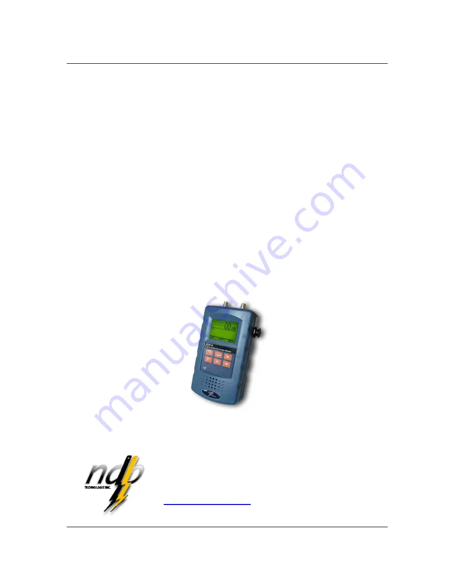
PARTIAL
DISCHARGE DETECTOR
XDP-II
User’s Guide
Version 7.2
March 2009
NDB Technologie Inc.
1405 St-Jean Baptiste St., suite 111
Québec, QC
G2E 5K2, Canada
Phone: (418) 877-7701
Fax: (418) 877-7787
http://www.ndbtech.com


