


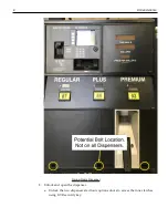


Kit Deinstallation
19
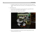
4. Repeat all previous steps for Side B of the dispenser if present. All cables must be
disconnected from the Options Doors and Printers before continuing the
deinstallation process.
Remove Internal Components
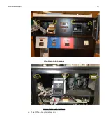
1. Disconnect the PowerCable. (Side A only)
a. Determine type of Dispenser. Dispenser Power Option 1 will have a Power Bus
and CRIND comm cable tied together. Dispenser Power Option 2 will have
connections directly to the transformer and a CRIND comm cable.
b. Follow the respective steps once the power option is identified.
Dispenser Power Option 1
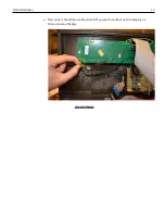
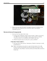
a. Disconnect the Comm and Power cable harness. Mark the connections to install
the OPTIC power.
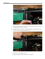
Note:
Some dispensers may also have a ground cable attached to the Cable
Harness or Electronics Sled. Disconnect this grounding wire if present. Some
dispensers may have different connection solutions but all will still be attached to
the bus line.
Содержание Retrofit OPTIC 5 Touch
Страница 10: ...viii...
Страница 12: ...x...
Страница 14: ...2...
Страница 16: ...4...
Страница 18: ...6...
Страница 23: ...Kit Deinstallation 11 Wide Frame Latch Locations Narrow Frame Latch Locations d Open the large dispenser door...
Страница 26: ...14 Kit Deinstallation Monochrome Display b Disconnect ribbon cable from the Card Reader...
Страница 38: ...26 Kit Deinstallation b Unbolt the sled rails and discard Move to the installation steps...