background image

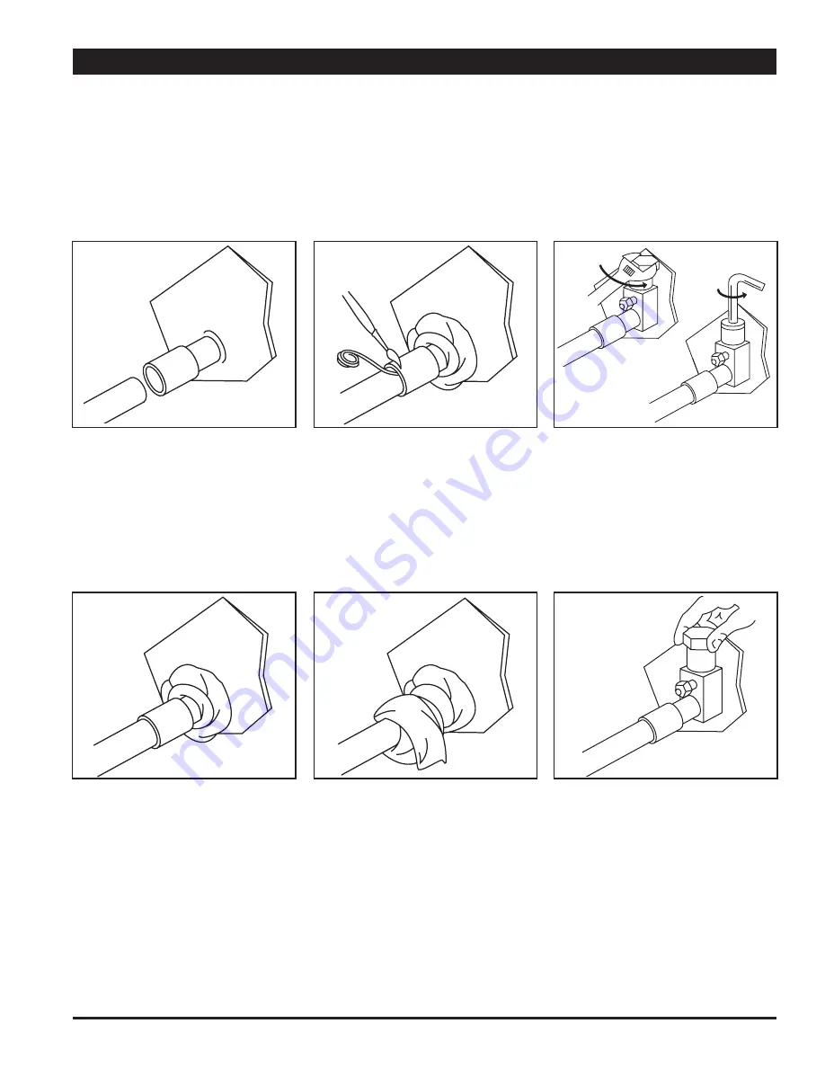
Figure 1 - Installing Refrigerant Lines

Field Installation:

Install the outdoor and indoor units 

per the manufacturer’s recommendations. 

Route the copper lines between the units.

3

Step 1:

The  tubing  should  be  cut 

square.  Make sure it is round 

and free of burrs at the con-

necting ends.  Clean the tub

-

ing  to  prevent  contaminants 

from entering the system.

Step 3:

Flux  the  copper  tube  and  in

-

sert into the stub.  Braze the 

joint.  No flux is necessary if a 

low to zero-silver braze alloy 

is used.

Step 5:

This  is  not  a  back  seating 

valve.  To open the valve re-

move  the  valve  cap  with  an 

adjustable  wrench.  Insert  a 

3/16” or 5/16” hex wrench into 

the stem.  Back out counter-

clockwise until the valve stem 

just  touches  the  retaining 

ring.

Step 2:

Wrap  a  wet  rag  around  the 

copper stub before brazing.

Step 4:

After  brazing,  quench  with  a 

wet rag to cool the joint and 

remove  any  flux  residue.  

Evacuate,  purge  or  charge 

the  connecting  lines  per  the 

unit  manufacturer’s  instruc

-

tions.

Step 6:

Replace the valve cap finger 

tight  then  tighten  an  addi

-

tional 1/12 turn or 1/2 hex flat.  

A metal-to-metal seal is now 

complete.    Complete  normal 

factory recommended proce-

dures.

Содержание NCHP-018

Страница 1: ...st be 3 flashed Bottom flashing to cover the full foot print of unit and extend up 2 on 3 sides All openings around the top sides and bottom must be caulked and sealed Care must be taken not to plug the openings in the front of the base pan of the unit If the optional wall sleeve is used caulk the spaces between the sleeve and the wall Completely fill the clearance between the unit and the wall sl...

Страница 2: ...haust air Important The outdoor unit is fully charged at the factory for the recom mended model of indoor unit With other models of indoor units the charge must be adjusted Be sure both service valves are closed during tubing installation and leak checking to avoid loss of charge A biflow liquid filter drier must be installed in the liquid line SPORLAN HPC 103 C or similar The unit has internally ...

Страница 3: ...e alloy is used Step 5 This is not a back seating valve To open the valve re move the valve cap with an adjustable wrench Insert a 3 16 or 5 16 hex wrench into the stem Back out counter clockwise until the valve stem just touches the retaining ring Step 2 Wrap a wet rag around the copper stub before brazing Step 4 After brazing quench with a wet rag to cool the joint and remove any flux residue Ev...

Страница 4: ...vent high head pressure which would shut down the unit Connect the charging cylinder to the manifold gauge set 1 Open the charging cylinder valve and bleed air out of the charging hose at the manifold gauge set connection Tighten the manifold gauge set charging connection Open 2 the main manifold gauge set valve and introduce refrigerant into the system Step 4 Evacuation Step 5 Refrigerant Chargin...

Страница 5: ...an to resume operation If the outdoor temperature is cold enough to produce icing on the outdoor coil during the heating mode approximately 34 the condensate heater will be energized through the heater thermostat located in the control box This heater stays ener gized during cold weather to keep any defrosted water from re freezing in the pan The condensate pan under the coil must be piped per ite...

Страница 6: ...90 42 38 35 33 30 29 26 24 21 19 17 14 95 33 38 35 33 31 29 27 24 22 20 18 15 75 96 39 36 34 32 29 27 25 22 20 18 15 80 76 39 37 35 32 30 28 26 24 22 19 18 85 60 39 37 35 33 31 29 26 24 22 20 18 90 48 40 38 35 33 31 29 26 24 22 20 18 95 38 40 38 36 33 31 29 27 25 22 20 18 80 84 42 40 38 36 34 32 30 28 27 25 23 85 67 42 41 39 37 35 33 31 29 27 25 23 90 54 44 42 40 38 36 34 32 31 29 27 25 95 43 45 4...

Страница 7: ...Figure 2 Wiring Schematic Heat Pump Units NCHP 018 024 030 1019 3019 7 ...

Страница 8: ...1 2 18 1 2 3 8 5 8 3 4 26 28 1 2 18 1 2 3 8 3 4 3 4 26 28 5 8 18 1 2 3 8 3 4 3 4 Width Height Length Liquid Valve Vapor Valve Drain Connection MPT CAP COOLING 18 000 24 000 28 500 CAP HEATING 47 F 17 000 22 500 26 000 ELECTRICAL 208 230 60 1 12 14 6 25 208 230 60 1 12 17 7 30 208 230 60 1 12 19 8 30 Volts Hertz Phase Min AWG Wire Min Cir Ampacity Max Fuse COMPRESSOR 7 0 41 9 9 61 10 7 61 RLA Amps ...

Страница 9: ... 3 4 23 3 4 32 18 1 2 3 8 3 4 3 4 23 3 4 32 18 1 2 3 8 3 4 3 4 Width Height Length Liquid Valve Vapor Valve Drain Connection MPT CAP COOLING 18 000 24 000 29 000 CAP HEATING 47 F 17 000 22 500 26 000 ELECTRICAL 208 230 60 1 12 14 6 25 208 230 60 1 12 17 7 30 208 230 60 1 12 19 8 30 Volts Hertz Phase Min AWG Wire Min Cir Ampacity Max Fuse COMPRESSOR 7 0 41 9 9 61 10 7 61 RLA Amps LRA Amps FAN MOTOR...

Страница 10: ...ESCRIPTION NCPC 018 NCPC 024 NCPC 030 11 12 13 14 15 16 17 18 19 20 21 Outdoor Coil Blower Motor 0 25 HP 1140 RPM 0 50 HP 1575 RPM Blower Wheels 7 6 OD x 8 0 Blower Housings Inlet Ring 2 req d Motor Blower Mount Access Panel 1000 Top Panel 1000 Right Side Panel Left Side Panel Wire Grille 1000 14208028 14270038 N A 14267007 14214013 14214021 14256933S 14256936Y 14256939S 14256938HP 14256937HP 1426...

Страница 11: ... DESCRIPTION NCHP 018 NCHP 024 NCHP 030 11 12 13 14 15 16 17 18 19 20 21 Outdoor Coil Blower Motor 0 25 HP 1140 RPM 0 50 HP 1575 RPM Blower Wheels 7 6 OD x 8 0 Blower Housings Inlet Ring 2 req d Motor Blower Mount Access Panel 3000 Top Panel 3000 Right Side Panel Left Side Panel Wire Grille 3000 14208026 14270038 N A 14267007 14214013 14214021 14256933S 14256969S 14256967S 14256973S 14256974HP 142...

Страница 12: ... that defective parts be returned to verify and identify the cause of the defect LIMITATION OF WARRANTIES ALL IMPLIED WARRANTIES INCLUDING IMPLIED WARRANTIES OF MERCHANTABILITY ARE HEREBY LIMITED IN DURATION TO THE PERIOD FOR WHICH EACH LIMITED WARRANTY IS GIVEN SOME STATES DO NOT ALLOW LIMITATIONS ON HOW LONG AN IMPLIED WARRANTY LASTS SO THE ABOVE LIMITATIONS MAY NOT APPLY TO YOU THE EX PRESSED W...

Страница 13: ... have to wait for a replacement compressor to be shipped from Bensalem PA The situation may present itself where it is better for the compressor to be returned to National Comfort Products during the 20 month Bristol warranty period NCP will also honor the Bristol 20 month warranty period All returned compressors must have the tubing connections closed with rubber plugs or brazed shut National Com...

Страница 14: ...seamless rifled copper tubes CABINET Unit cabinet shall be constructed of heavy gauge galvanized or aluminized steel The steel shall be treated by phosphate washes prior to electrostatically applied and oven baked paint FACTORY CHARGED Each unit shall be charged with R 22 for proper operation with recommended indoor coil and 10 foot tubing SERVICE VALVES Each unit shall be equipped with liquid and...

Страница 15: ...SPLIT SYSTEM HEAT PUMP INSTALLATION INSTRUCTIONS Rev 09 09 ...

Страница 16: ......

Отзывы: