Installing Additional Memory
Installing Optional Equipment in the Space-Saver Base
5-5
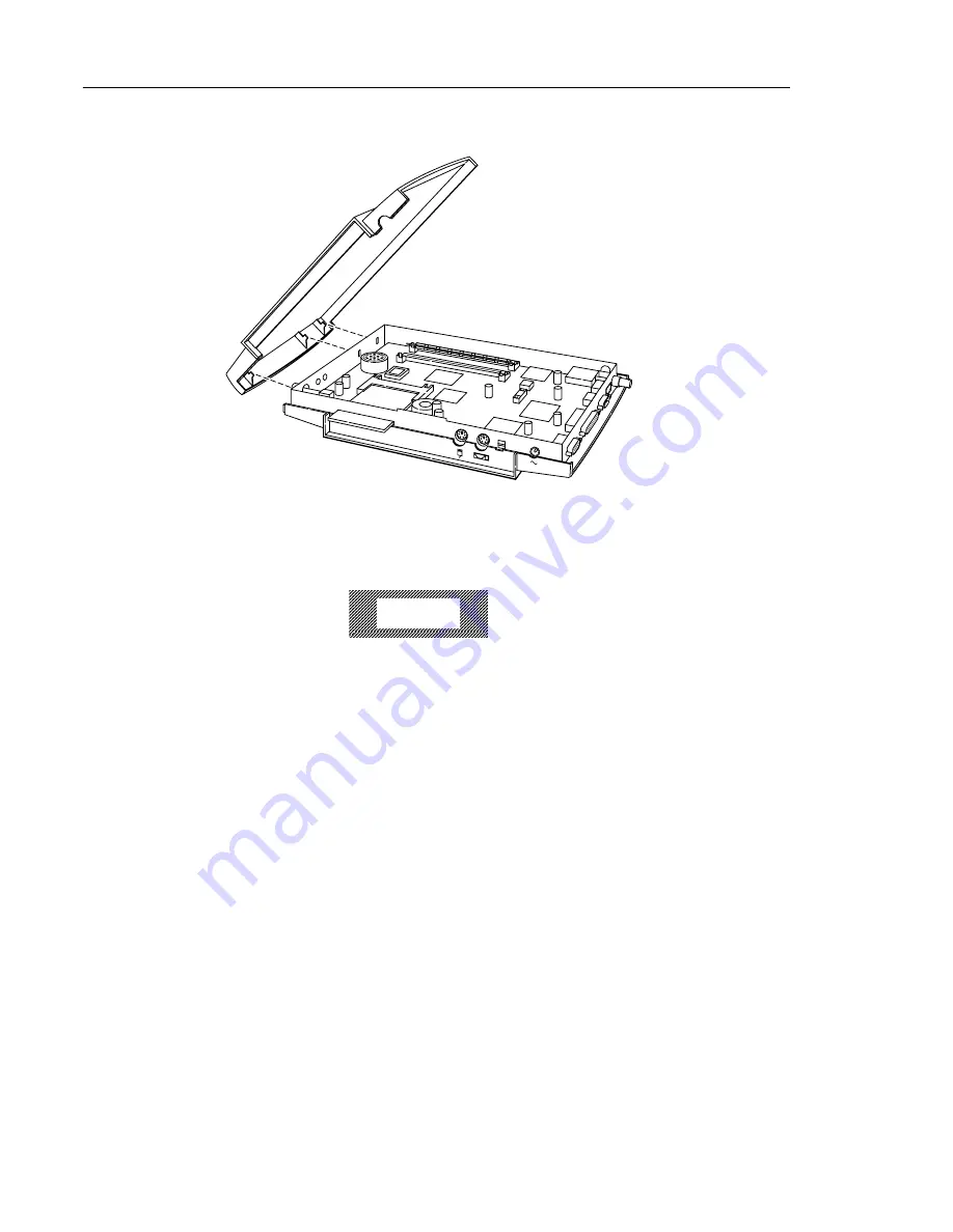
6. Lift the top section at the front up so that you can separate the top’s hooks
from the bottom section’s slots. Remove the top. See Figure 5-3.
Installing SIMMs
Caution
Electrostatic Discharge (ESD) can damage SIMMs and other components located
on the logic board. Make sure you touch a suitable ground before handling any
SIMM. If possible, set the NC on an anti-static mat and wear a grounding strap.
Always handle SIMMs
only
by the edges.
Your
NC
already has a
SIMM
or
SIMM
s installed. The
SIMM
slots, located on
the left side of the logic board, are labeled J9 and J10. (See Figure 5-4.) Observe
the
SIMM(
s) currently in the slots and refer to Table 5-1, “Memory
Configurations,” on page 5-2 to determine your configuration. Decide what
you want your new configuration to be. If you need to remove an existing
SIMM
, go to “Removing SIMMs” on page 5-7 and then return to this section
for installation instructions.
Figure 5-3 Separating the Top from the Bottom
Содержание Explora 450 Series
Страница 6: ......
Страница 14: ...2 2 Explora 400 450 Series Product Line...
Страница 40: ...Installing the Security Device and Mounting Bracket 5 14 Installing Optional Equipment in the Space Saver Base...
Страница 62: ...In Case of Trouble 8 4 Troubleshooting...


