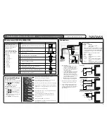
Overview of the Keys
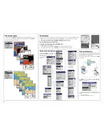
Selecting an item in a menu
The TRACKFISH is operated by selecting
items from menus shown on the display.
1 Press or to move the highlight
to the item.
2 Press
ENTER
to select the item.
Changing a number or word
To change a number or word on the
display:
1 Press or to move the highlight
to the digit or letter to change.
Press or to change the digit or
letter.
2 Repeat the above step to change any
other digits or letters.
3 Press
ENTER
to accept the change.
1 Wire the power:
•
Either
Basic wiring
: When the main
switch is on, the TRACKFISH must be
powered on manually with the key.
The engine hours counter and fuel
counter are disabled.
•
Or
Auto power wiring
: The TRACKFISH
turns on and off automatically when
the ignition is turned on and off. The
engine hours counter and fuel counter
are enabled. Choose auto power when
the optional fuel kit is fitted.
Note
: With auto power, the TRACKFISH
can not be turned off using the key.
2 Wire any external beepers or lights. If the
current is more than 200 mA, fit a relay.
3 The power/data cable has a plug with a
black collar. Plug this plug into into the
connector with a black nut on the back of
the TRACKFISH. Turn the collar to lock
the connector.
In chart mode, centres chart at boat’s position.
Go back to an earlier menu or display.
Show a menu of the main displays. To go to a display,
select it from the menu (see section 2-7).
Cursor keys, to move the cursor or the selection highlight.
Show a menu of the options for the current display. Press
again to display the Setup menu (see section 17).
Start an action or accept a change.
Chart display: Zoom in or out to display different areas
and detail on the chart.
Sonar display: Change the depth range displayed.
Switch the display to the next in the favourites list
(see section 2-7-2)
Man overboard (MOB, see section 2-4).
Turn TRACKFISH on and off (see section 2-2); adjust the
backlighting (see section 2-3).
Optional fuel
sensor
GPS antenna
Transom mount
dual frequency
transducer
Connections
Black connector
Blue connector
Yellow connector
GPS antenna
Optional cable setup
Power/data cable
Pin Wire
Function
1 Black
Ground: power negative,
NMEA ground
Note
: The cable has two wires with black coverings,
the black wire (pin 1) and the shield (covered with
heatshrink). These wires are connected within the
cable and therefore it does not matter which black
wire you use.
2 Brown
Power out, 9 V DC (NOT USED)
3 White
NMEA out
4 Blue
NavBus
-
5 Red
Positive power in, 10.5 to 32 V DC
6 Orange
NavBus
+
7 Yellow
Auto power in (connect to red wire
[positive power in] to enable Auto
power).
8 Green
External beeper or light out, switched
to ground, 30 V DC 200 mA maximum.
Fuse 2 A
Red
Black
Main
switch
12/24 V DC
Basic wiring
Power/data
cable
Main
switch
Fuse 2 A
Red
Yellow
Black
Auto power wiring
Power/data
cable
Fuse 2 A
Ignition
switch
Ignition
12/24 V DC
Red
Green
Wiring external beepers or lights
Power/data
cable
External
beepers or
lights
What comes with the Trackfish 6500
Trackfish 6500 Quickstart Guide
w w w . n a v m a n . c o m
Getting started with your new TRACKFISH 6500
3
Part
* Dual Frequency sonar
transducer and manual only
available with transducer
included models.
**The full TRACKFISH 6500
instruction manual CD-ROM
is supplied in the following
languages:
• English
• Spanish
• Portuguese
• French
• Dutch
• German
• Italian
• Finnish
• Swedish
TRACKFISH display unit, with a holder for plug-in cards.
Dust cover for display unit
Marine Electronics
Power cable
Mounting bracket (screws included)
Warranty registration card
Navman 1240 GPS antenna
Flush mounting kit
Dual frequency transom sonar transducer *
(includes cable kit and screws)
Transom Mount Transducer Installation Manual *
Full Instruction Manual CD**
Marine Electronics


