background image

FISH 4350 / 4380 

Installation and Operation Manual

2

NAVMAN 

FCC Statement

Note: This equipment has been tested and found to comply with the limits for a 
Class B digital device, pursuant to Part 15 of the FCC Rules. These limits are 
designed to provide reasonable protection against harmful interference in a normal 
installation. This equipment generates, uses and can radiate radio frequency 
energy and, if not installed and used in accordance with the instructions, may cause 
harmful interference to radio communications. However, there is no guarantee that 
interference will not occur in a particular installation. If this equipment does cause 
harmful interference to radio or television reception, which can be determined 
by turning the equipment off and on, the user is encouraged to try to correct the 
interference by one or more of the following measures:

    Reorient or relocate the receiving antenna.

    Increase the separation between the equipment and receiver.

    Connect the equipment into an output on a circuit different from that to 

which the receiver is connected.

    Consult the dealer or an experienced technician for help.

    A shielded cable must be used when connecting a peripheral to the 

serial ports.

IMPORTANT

It is the owner’s sole responsibility to install and use the instrument and transducers in a 
manner that will not cause accidents, personal injury or property damage. The user of this 
product is solely responsible for observing safe boating practices.
NAVMAN NZ LIMITED DISCLAIMS ALL LIABILITY FOR ANY USE OF THIS PRODUCT IN A 
WAY THAT MAY CAUSE ACCIDENTS, DAMAGE OR THAT MAY VIOLATE THE LAW.
Governing Language: This statement, any instruction manuals, user guides and other 
information relating to the product (Documentation) may be translated to, or has been translated 
from, another language (Translation). In the event of any con

ß

 ict between any Translation 

of the Documentation, the English language version of the Documentation will be the of

Þ

 cial 

version of the Documentation.

Fuel Computer:

 Fuel economy can alter drastically depending on the boat loading and 

sea conditions.  The fuel computer should not be the sole source of information concerning 
available fuel onboard and the electronic information should be supplemented by visual or 
other checks of the fuel load. This is necessary due to possible operator induced errors such 
as forgetting to reset the fuel used when 

Þ

 lling the tank, running the engine with the fuel 

computer not switched on or other operator controlled actions that may render the device 
inaccurate. Always ensure that adequate fuel is carried onboard for the intended trip plus a 
reserve to allow for unforeseen circumstances.
This manual represents the FISH 4350 and FISH 4380 as at the time of printing. Navman NZ 
Limited reserves the right to make changes to speci

Þ

 cations without notice.

Copyright © 2003 Navman NZ Limited, New Zealand. All rights reserved. Navman is a registered 
trademark of Navman NZ Limited.

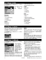
The FISH 4350 and FISH 4380 are set up with default units of feet, °F (Fahrenheit), 
US gallons and knots. See section 3-7 Setup > Units, to change the units.

Содержание Fish 4350

Страница 1: ...English 2 Espa ol 28 Portugu s 59 NAVMAN w w w n a v m a n c o m F I S H 4 3 5 0 4380 F I S H F I N D E R Installation and Operation Manual...

Страница 2: ...ing practices NAVMAN NZ LIMITED DISCLAIMS ALL LIABILITY FOR ANY USE OF THIS PRODUCT IN A WAY THAT MAY CAUSE ACCIDENTS DAMAGE OR THAT MAY VIOLATE THE LAW Governing Language This statement any instructi...

Страница 3: ...4 Using the FISH 4350 and FISH 4380 13 4 1 Interpreting the display 13 4 2 Fish detection and display 16 4 3 Gain 17 4 4 Range 18 5 The Displays 18 5 1 Sonar display 19 5 2 Sonar Zoom display 19 5 3 S...

Страница 4: ...IMPORTANT NOTE ON USE While any sh nder can be used as an aid to navigation accuracy can be limited by many factors including the location of the transducer It is the user s responsibility to ensure...

Страница 5: ...No transducer detected Enter simulate mode will appear Press or to select and press to accept If the transducer was not intentionally disconnected turn off the sh nder and refer to the section on Tro...

Страница 6: ...e fishfinder generates data so that all the main displays appear to be operational Use Setup Simulate as follows 1 Press MENU twice to show the Setup menu 2 Highlight Simulate 3 Press to select On or...

Страница 7: ...the keys in more detail The Setup menu and options are summarized below The factory default settings are shown where applicable Each Setup menu option is explained in the following sections The Setup...

Страница 8: ...to 2 hours The sh nder appears to turn off however all alarms operate normally To return to normal operation press any button Ideal to be used as an anchor alarm Factory reset This option returns all...

Страница 9: ...n the palette represents a different echo strength as shown on the sonar displays There is a choice of ve colour palettes Black Blue White Vivid and 8 colour The rst four display more detail whilst th...

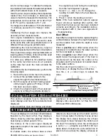
Страница 10: ...see section 5 5 Fuel Display and the Low Fuel Alarm see section 3 6 Setup Alarms are meaningless Set remaining Before doing a partial re ll of the tank or remov ing fuel manually from the tank for ex...

Страница 11: ...rms Press MENU twice to display the Setup menu then select Alarms Trigger settings can be de ned to suit the boat and individual preferences as follows Alarms can be set enabled to automatically detec...

Страница 12: ...s will be transmitted seeAppendixA Speci cations and section 5 6 Data display for information about how to display NMEA data Press MENU twice to display the Setup menu then select Calibrate The fuel o...

Страница 13: ...eading to match that on the fuel dispens er s gauge 6 Press when the reading is correct Note If the fuel calibration options appear to give erroneous readings after a while rst check that the fuel sen...

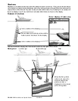
Страница 14: ...boat is anchored the echoes all come from the same area of bottom This produces a at bottom trace on the display The screen shot shows a typical sonar display with the Fish symbols turned Off covered...

Страница 15: ...for an example of the sonar display in such an environment A double bottom trace is shown on the display Sonar display of same area sh is visible on the display sh is hidden by the strong echoes off...

Страница 16: ...e can form a barrier which the sh may not swim through In fresh water sh often collect around a thermocline Fish symbols The sh symbol can be customized or switched off altogether so that the echoes a...

Страница 17: ...e sh passes out of the middle of the cone the reverse happens with a progressively weaker and deeper echo There are many reasons why sh arches may not be seen For example Poor transducer installation...

Страница 18: ...a that is magni ed Use the or cursor keys to adjust the zoom range Use the or cursor keys to adjust the zoom offset 5 The Displays Press MENU once to show the Display menu then select a particular dis...

Страница 19: ...n See section 4 4 Range for information about adjusting the Zoom Range and Zoom Offset Zoom bar Sonar history Zoom section Divider line 5 3 Sonar Bottom display To show the Sonar Bottom display highli...

Страница 20: ...h species The user can de ne the level of the weakest and strongest echoes to be shown on the sonar Divider line between sonar history and A Scope Gain setting strongest echo for display Gainthreshold...

Страница 21: ...y unit Power cable Mounting bracket screws included Warranty registration card This manual Sun cover for display unit Flush mounting kit Transom transducer includes cable kit and screws Transom Mount...

Страница 22: ...ensure that the plugs left in the boat are not exposed to the elements Push the attached dust covers over the exposed ends of the plugs Keep the display unit in a dry clean place such as the optional...

Страница 23: ...l transducer cable Wire the power cable for Auto power as described in this section to make sure the fuel counter starts as soon as the engine starts For twin engine installation a T connector needs t...

Страница 24: ...rature 32 to 122 F 0 to 50 C Transom transducer cable length FISH 4350 33 ft 10 m FISH 4380 26 ft 8 m Typical depth acquisition time from startup 2 seconds at 100 ft 30 m Receiver sensitivity Better t...

Страница 25: ...cuit see section 6 5 Wiring options f Check for corrosion on the power cable connector and clean or replace if required g Check fuses that are placed in line with the power cable A fuse can be blown d...

Страница 26: ...but nothing is displayed The sh nder may be operating but the backlight settings may have been set too low See section 2 Basic Operation to adjust the sh nder backlight Press twice 8 The wrong langua...

Страница 27: ...k that the value is not set to zero thentryincreasingthevalueuntilasteady ow rate is shown See section 3 3 Setup Fuel 13 There is no reading for fuel economy a The boat must be travelling through the...

Страница 28: ...Singapore Malaysia Brunei Indonesia and Phillipines RIQ PTE Ltd Blk 3007 81 Ubi Road 1 02 440 Singapore 408701 Ph 65 6741 3723 Fax 65 6741 3746 e mail riq postone com Taiwan Sea rst International Corp...

Страница 29: ......

Страница 30: ...Lon 174 44 535 E Lat 36 48 404 S Made in New Zealand MN000240B NAVMAN FISH 4350 and FISH 4380...

Отзывы: