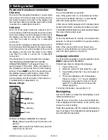


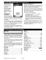


FISH 4100 Installation and Operation Manual
NAVMAN
19
Warning
1 Amp fuses must be positioned where shown in
the wiring diagrams.
If possible, route the transducer cables away from
other wiring on the boat. Electrical noise from engine
wiring, bilge pumps and other electrical equipment
can affect the unit.
The shortest and most direct connection to the boat's
battery helps to minimize voltage drop. Do not lay
cable along the bilge.
Two wiring options are described in this section:
·
Basic Wiring. This does not start the fishfinder
automatically when the boat ignition is
switched on and it disables the engine hours
counter.
·
Auto Power Wiring. This must be used for
engine hours and fuel computer options.
Important
The NAVMAN fishfinder must be run off a 12 volt
battery and must not be run off a circuit without a
battery.
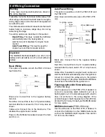
Basic Wiring
This option is possible on both the FISH 4100 and
the FISH 4150.
Auto Power Wiring
This option is possible on both the FISH 4100 and
the FISH 4150.
Note: Green and white wires are on the FISH 4150
only.
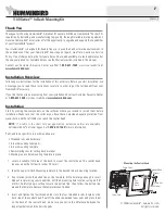
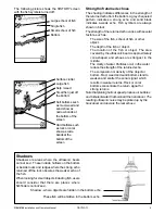
5-4 Wiring Connection
Fuse
Fuse
Fuse
Red
Yellow
Black
Main
switch
12 V DC
Black wire: Connect this to the negative battery
terminal.
Red Wire: Connect this to the 12 V positive battery
terminal after the main switch. Fit a 1 Amp fuse as
shown.
Yellow wire: Connect this to the black wire. This
disables the engine hours counter.
Power on the fishfinder manually whenever the main
switch is on.
Black wire: Connect this to the negative battery
terminal.
Red Wire: Connect this to the 12 V positive battery
terminal after the main switch. Fit a 1 Amp fuse as
shown.
Yellow Wire: To enable the engine hours counter and
start the fishfinder automatically when the ignition is
turned on, connect the yellow wire to the ignition
system, through a 1 Amp fuse. Note that the fishfinder
cannot be turned off while the ignition is on.
Flashing Light and/or External beeper
(FISH 4150 only)
Use the green wire on the FISH 4150, if desired, to
connect a secondary alarm indicator such as a
flashing light or a 12 V external beeper with a built in
drive circuit. Refer to the wiring diagram. If the
external beeper or light requires more than 250 mA
dc total, fit a 12 V relay. Consult your NAVMAN dealer
for more advice.
NMEA Instruments (FISH 4150 only)
Use the white wire on the FISH 4150, if desired, to
connect the fishfinder to other NMEA instruments
such as the NAVMAN depth repeater. See section
5-5 for more information.
White (NMEA out)
Green
External Beeper
or Light
Red
Yellow
Black
Main
switch
12 V DC
Ignition
switch
To ignition system