


10 |
Installation |
Loop S User Manual
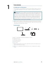
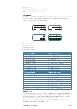
System IDs
System
Egon +
boards
Controlable
outputs
Monitored power
outputs
Drop-cable ID
Loop S
1
8
8
CAN ID: 1
Loop S+
2
16
16
CAN ID: 1
CAN ID: 2
Egon+ board
!
Warning:
For details about maximum load and other specifications,
refer to the “Technical Specifications” on page 24. Exposing the unit to
conditions that exceeds the specifications could invalidate your warranty.
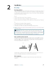
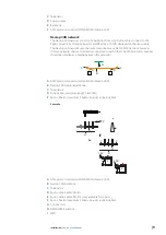
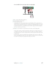
Connector overview
A
B
C
D
E
F
A
Naviop CAN connector
B
Main power input (2x M8 studs)
C
Output port 4 (green)
D
Output port 3 (blue)
E
Output port 2 (gray)
F
Output port 1 (black)
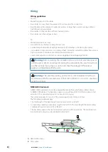
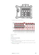
Relay and fuse overview
All relays and fuses can be found under the protective cover. The Egon+ board is equipped
with 12 V DC rated relays. The input voltage should match the voltage rating of the relays.
!
Warning:
IGNITION PROTECTED
ONLY WHEN EQUIPPED WITH
IGNITION PROTECTED FUSES AND COVER CLOSED.
ANY REPLACEMENT FUSES MUST BE IGNITION PROTECTED
. COVER
MUST BE CLOSED IN EVERY OPERATIONAL CONDITION!
!
Warning:
• Always use a fuse that is appropriate for the connected load, the supplied
fuses may have to be replaced to match the outputs connected load.
Using an incorrect fuse size compromises the safety of the electrical
system on board and increases the risk of electrical fire.
• Fuse installation and replacement must be done by expert technicians.
• Replace fuses in a ventilated area.
• All replaced fuses must be ignition protected fuses.
• Do not replace a fuse by short circuiting the poles in the fuse sockets.
• Do not short circuit the poles of the relay sockets.
Содержание Loop S
Страница 1: ...ENGLISH LoopS User Manual www bandg com www simrad yachting com www lowrance com ...
Страница 2: ......
Страница 26: ......
Страница 27: ... 988 12393 002 www bandg com www simrad yachting com www lowrance com ...


