background image

16        About the Boiler

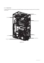
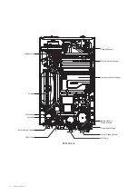
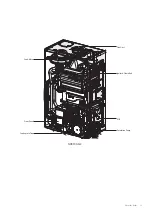
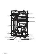
Air In

Air In

Exhaust 

Gas

Blow Fan

Ignitor

Gas 

Valve

Gas 

Inlet

Flow 

Out

CH 

Return

Three 

-way 

Valve

DHW Heat 

Exchanger

Circulation 

Pump

Heat 

Exchanger

2.6.2    Operating According to Outdoor 

Temperature Conditions

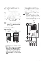
The Outdoor Reset Control feature may be used to enhance 

energy efficiency while maintaining optimal heating 

performance. With the Outdoor Reset Control, the central 

heating temperature setting automatically changes according to 

the outdoor temperature and the K-Factor setting.

You can configure the Outdoor Reset Control settings on the 

front panel in the Central Htg Operation menu. Refer to “10.6.2 

Setting the Central Heating Operation on page 45.

Note

The Outdoor Reset Control feature requires 

installation of an outdoor temperature sensor, and it 

only works when the boiler is running in the normal 

operation mode. It does not work when the boiler’s 

front panel displays a fault.

2.6    Operating Modes

2.6.1    Operating in Central Heating Mode

To operate the central heating mode: 

1.  Press the Menu button (

) to access the Main menu and 

select “2. Central Htg Operation” by pressing the OK button 

(

).

2.  In the Central Htg Operation menu, select “1. Central Htg 

ON/OFF” and select “Enable”. Then, select “1-1 CH Set Temp” 

and select a heating temperature setpoint higher than 

current heating temperature. 


When the boiler detects a request for heating production 

(from the installation’s room thermostat, for example), the 

3-way valve goes to heating position and the circulating 

pump starts up.


If the boiler water temperature is lower than the desired 

temperature setpoint, the boiler ignites and heats up the 

heating installation until the selected boiler temperature 

is reached. The boiler’s electronic control modulates 

the burner output to adapt to the installation’s heat 

requirements at all times and so that the installation’s 

water temperature remains constant. This prevents the 

installation from overheating and reduces heat loss as 

much as possible.


When there is no further heating demand (e.g. when 

the desired ambient temperature selected on the room 

thermostat is reached), the burner is extinguished (if it was 

ignited) and the circulation pump continues to run during 

the post-circulation time (minimum 3 minutes), to protect 

the boiler from overheating due to thermal inertia in the 

installation.

Содержание NCB700-42C

Страница 1: ...warranty service always contact an official Technical Assistance Service TAS first Contact the technician or professional who installed your boiler Contact a Gas Safe Registered engineer When contact...

Страница 2: ...actly a fire or explosion may result causing property damage or personal injury Do not store or use petrol or other flammable vapours and liquids in the vicinity of this or any other appliance WHATTO...

Страница 3: ...Terminating the Flue 34 7 Setting the DIP Switches 35 7 1 PCB DIP Switches 35 7 2 Front Panel DIP Switches 35 8 Connecting Electrical Supplies 36 8 1 Accessing the Terminal Strips 36 8 2 Connecting t...

Страница 4: ...bour s phone call your gas provider and follow their instructions If you cannot reach your gas provider call the fire department Do not return to your home until authorised by your gas supplier or the...

Страница 5: ...explosion Do not place combustibles such as newspapers or laundry near the boiler or flue system Doing so may result in a fire Do not place or use hair sprays spray paints or any other compressed gas...

Страница 6: ...C Very low scald risk CAUTION Do not turn on the boiler unless the water and gas supplies are fully opened Doing so may damage the boiler Do not turn on the water if the cold water supply shut off va...

Страница 7: ...as If LPG conversion is required use the conversion kit supplied with the boiler and attach the item matching the LPG GC No included in the kit The Codes of good practice and regulations refer to the...

Страница 8: ...s When you no longer wish to use the boiler disable any parts that could be potentially hazardous A B C D E F G 2015 811 2013 dB kW A A A B C D E F G A A KD Navien NCB 24LDWE XL 20 40 Installation Ope...

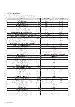
Страница 9: ...ey with burner switched on 1 9 1 9 Seasonal efficiency rate SEDBUK 2009 89 1 89 1 NOx Classification Class 6 Category II2H3P Type Heating and instantaneous hot water production Heat output adjustment...

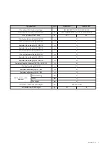
Страница 10: ...ow length 90 60 100 m 1 3 Equivalent elbow length 45 60 100 m 1 0 Max horizontal coaxial length 80 125 m 68 Max vertical coaxial length 80 125 m 70 Equivalent elbow length 90 80 125 m 2 2 Equivalent e...

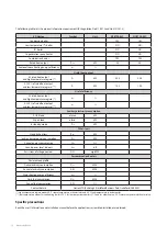
Страница 11: ...load elmin kW In standby mode PSB kW Other items Standby heat loss Pstby kW Ignition burner power consumption Pign kW Annual energy consumption QHE GJ Sound power level indoors LWA dB Emissions of nit...

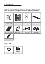
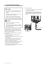
Страница 12: ...ollowing diagram shows the key components of the boiler Component assembly diagrams and particular parts lists are included in the Appendices Fan Motor Front Panel Flue Duct Ignitor Flame Rod Circulat...

Страница 13: ...Single Venturi Mixing Chamber Air Pipe Primary Heat Exchanger Secondary Heat Exchanger Return Adapter Filter Assembly 3 Way Valve Central Heating Return Pressure Relief Valve Central Heating Supply D...

Страница 14: ...About the Boiler 13 NCB700 54C Fan Motor Front Panel Flue Duct Ignitor Flame Rod Circulation Pump Condensate Trap PCB...

Страница 15: ...Single Venturi Mixing Chamber Air Pipe Primary Heat Exchanger Secondary Heat Exchanger Return Adapter Filter Assembly Gas Valve Central Heating Return Pressure Relief Valve Central Heating Supply DHW...

Страница 16: ...95 mm 440mm Supply Connections Description Diameter A Flue exhaust Air intake 60 100 80 125 B Central heating supply 22 mm C Hot water outlet DHW 15 mm D Gas supply inlet 22 mm E Cold water inlet DHW...

Страница 17: ...enu and select 2 Central Htg Operation by pressing the OK button 2 In the Central Htg Operation menu select 1 Central Htg ON OFF and select Enable Then select 1 1 CH Set Temp and select a heating temp...

Страница 18: ...ture range by k factor setting value and the applicable outdoor temperature range 20 15 10 5 0 10 15 20 25 5 20 30 40 50 60 50 70 80 90 4 3 5 3 2 5 2 1 5 1 2 0 6 1 0 2 Outdoor Temperature C Outdoor Te...

Страница 19: ...boiler in its final location A detailed description is given of the procedure in the sequenced sections below Wall mounting Gas connection Electrical connections DIP switch settings Final check Water...

Страница 20: ...ainage The boiler produces a significant amount of condensate during operation This condensate must be removed from the boiler and suitably treated if national legislation so requires The boiler shoul...

Страница 21: ...boiler in areas where petrol or other flammables are used or stored Ensure that combustible materials are stored away from the boiler and that hanging laundry or similar items do not obstruct access...

Страница 22: ...the tongues on the mounting bracket and hang the boiler on the bracket When mounted with the mounting bracket the boiler will have a 16 mm clearance from the back of the wall WARNING The boiler is he...

Страница 23: ...d cause leaks Any dirt in the tubes could reduce boiler efficiency and cause it to malfunction Any pipes exposed to the elements or which could freeze in winter must be insulated with suitable insulat...

Страница 24: ...3 5 Follow all local codes and regulations when disposing of condensate from the boiler We recommend draining the condensate into a laundry tub as the alkali in laundry detergent will neutralise the...

Страница 25: ...terial for the drain line such as PVC or CPVC Do not reduce the size of the drain line to less than 21 5 mm The drain line can be connected to the condensate trap using a condensate trap hose The hose...

Страница 26: ...e normally after performing an air purge 4 7 Testing the Water System WARNING Ensure that the boiler is full of water before firing the burner Operating the unit without filling it will damage the boi...

Страница 27: ...owing recommendations must be complied with at the least Before installing the gas pipes check the type of gas is compatible with the boiler Check that the gas meter in the home can measure the rate o...

Страница 28: ...lace away from direct sunlight It must also be thoroughly secured to prevent it from tipping over which could cause an explosion If the boiler is used with propane a gas regulator suitable for this ty...

Страница 29: ...t gas pressure reading on the manometer The gas pressure must fall within the ranges specified on page 8 3 Leave the faucet on until the boiler shuts down due to a lack of gas supply and then turn off...

Страница 30: ...connecting the flue outlet must be correctly joined using sealing gaskets Ensure that there are no leaks from any part of the removal circuit Switch off the boiler and wait for the pipes to cool down...

Страница 31: ...ear any overhangs 6 2 Selecting a Flue System WARNING The gas removal ducts must not be in contact with or near flammable materials and they must not pass through any structures or walls of buildings...

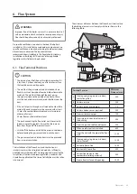
Страница 32: ...00 or 1 000 851 140 min Wall Extended Removal System 80 125 Max length A B 1 x 90 elbow 68 2 2 65 8 m 60 100 Max length A B 1 x 90 elbow 20 1 3 18 7 m B A 80 125 Max length A B 1 x 45 elbow 68 1 67 m...

Страница 33: ...System 80 125 Max length A B 1 x 45 elbow 70 1 69 m 60 100 Max length A B 1 x 45 elbow 21 1 20 m A B Minimum 350 mm Pipe Diameter mm Maximum Length m Elbow Equivalent Length m 60 100 21 45 1 0 80 125...

Страница 34: ...110 2 x 1 4 107 2 m D C A B Minimum 370 mm Pipe Diameter mm Maximum Length m Elbow Equivalent Length m 80 80 110 45 1 4 Extended Removal System 80 80 Max length A B C D E F 4 x 90 elbow 110 4 x 2 2 10...

Страница 35: ...l terminal The total length of the tubes must not exceed the maximum value defined If the removal installation includes elbows while calculating the total length you must take into account that each e...

Страница 36: ...board configures boiler type capacity burner type country and discharge of condensate function 1 2 3 4 5 6 7 8 ON DIP SW1 Switch Function Setting 1 Boiler Type SOLO ON COMBI OFF 2 Reserve 3 4 Capacity...

Страница 37: ...t the time of installation Note The NCB700 boiler has an electrical protection degree of IPX5D The electrical connection must be made via a bipolar switch located on the same premises as the boiler Th...

Страница 38: ...ether with the seal B 4 Insert all these elements in the cable gland and press on the lid A until the cable is sufficiently fixed in place and the unit is sealed Note The boiler must be connected to t...

Страница 39: ...lock is not required Simply connect the Navien Smart Room Controller cable to the 2 pin connector Note You need to install an app on your mobile device to control the boiler from your mobile device Re...

Страница 40: ...ngeover check the gas inlet pressure Check that the gas circuit is hermetically sealed Check that the control panel is working correctly Check that it functions normally when the boiler is switched on...

Страница 41: ...r s schedule programming operation is set f DHW preheat Displayed when the DHW preheat feature is enabled DHW preheat DHW Intelligent DHW preheat Always on DHW preheat Weekly DHW preheat off Eco mode...

Страница 42: ...al heating and DHW supply temperatures Refer to the following table for detailed information a b c d e f a Menu button Access to the Main menu screen b Back button Access to the previous screen c OK b...

Страница 43: ...rt up wizard The temperature will appear on the front panel display after the power is turned on 10 3 Start Up Wizard The setup wizard should run the first time the unit is powered on The wizard must...

Страница 44: ...r temperature 1 Make sure that all hot water taps are closed and ensure that the internal circulator and any external circulating pumps are off 2 In normal operation mode press the Up button The DHW t...

Страница 45: ...ote The fan motor controls the APS so the fan target speed Fan Target RPM is only for your reference 10 6 Accessing Basic Menu Items In the Main Menu screen you can view the boiler s operating conditi...

Страница 46: ...input from the outdoor temperature sensor OTC Outdoor Temperature Compensation control will be enabled automatically Also if there is no input from the outdoor temperature sensor OTC control will be d...

Страница 47: ...gramming operation press the Menu button and then select 4 Schedule Programming 10 6 3 Setting the DHW Operation To set the boiler s DHW operation press the Menu button and then select 3 DHW Operation...

Страница 48: ...ch between the list items or to increase decrease setting values Press the OK button to select an item or to confirm after making changes Press the Back button to return to the previous screen or menu...

Страница 49: ...System Information To view the miscellaneous system information press the Menu button and then select 6 EMS Data Press the Up button or the Down button to switch between the information items Press t...

Страница 50: ...u Items 10 7 1 Viewing Service Information To view the service information about the boiler press the Back button and the Menu button simultaneously for 3 seconds and then select 1 Service Status Info...

Страница 51: ...20 min Default 3 min 8 Freeze protection Set the pump freeze protection temperature Setting range 6 C 10 C Default 10 C Note The system freeze protection temperature is set based on the pump freeze p...

Страница 52: ...it Setting range Central heating minimum capacity central heating minimum capacity limit 20 Default Boiler s minimum heat capacity 11 CH Max Limit Set the central heating maximum heat capacity limit S...

Страница 53: ...iler to run in 2nd stage minimum operation mode Press the Up button or the Down button to switch between the test procedures Press the OK button to run a test procedure Note During the test mode the b...

Страница 54: ...E353 Abnormal operation Water pressure sensor Auto DHW Circulation E407 DHW Outlet thermistor Open or Short Circuit Alarm E421 DHW Inlet thermistor Open or Short Circuit Auto E434 Abnormal operation F...

Страница 55: ...l need to drain either both the central heating side and domestic hot water DHW side or one side only before performing maintenance tasks such as cleaning the adapter filter or to prevent the boiler f...

Страница 56: ...s still connected Do not close the gas valve except for routine maintenance as this will limit additional freeze protection If the boiler will not be used for an extended period drain the boiler If th...

Страница 57: ...beginning of every heating season and or when there is a problem 11 5 Maintenance Schedules Owner maintenance Daily Check boiler area Check pressure temperature gauge Monthly Check flue piping Check...

Страница 58: ...may also cause severe property damage 1 Inspect all water and gas piping and verify to be leak free 2 Look for signs of leaking lines and correct any problems found Checking the Flue System and Air P...

Страница 59: ...Remind the owner to follow the proper shutdown procedure and to schedule an annual start up at the beginning of the next heating season WARNING Failure to inspect for the above conditions and have th...

Страница 60: ...ive is engaged in and is responsible for the connection utilization repair or servicing of gas utilization equipment or accessories who is experienced in such work familiar with all precautions requir...

Страница 61: ...ssembly 8 With the internal components exposed locate the gas inlet pipe and the gas valve in the middle of the unit as shown in Figure 2 1 and Figure 2 2 Gas Valve Gas Inlet Pipe Figure 2 1 NCB700 42...

Страница 62: ...exposed remove the two screws that hold the part in place Remove the Gas Orifice from its housing and prepare the new Gas Orifice for the LP conversion for installation Remove 2 screws here Figure 4 A...

Страница 63: ...inal position and use all screws to secure all connections Note Do not overtighten as this may damage or crack the components 12 Check the labels carefully and then connect all the wires 13 Set the fr...

Страница 64: ...value is not within 0 5 of the value listed in Table 2 the gas valve set screw will need to be adjusted If adjustment is necessary locate the set screw as shown in Figure 8 Using a 5 32 in or 4 mm All...

Страница 65: ...off To properly maintain the boiler you should clean the heat exchanger annually To clean the heat exchanger 1 Press the Power button on the front panel to turn off the boiler 2 Disconnect the power s...

Страница 66: ...the front panel Note When removing the front panel label all wires and make sure all wires are disconnected 7 Use a Phillips screwdriver to remove the four screws where gas inlet pipe is attached to t...

Страница 67: ...important to keep electric parts of the boiler safe from water Navien recommends to use a hose If the water pressure of the hose is too high water may splash to other electric parts of the boiler Kee...

Страница 68: ...emp Dip s w 8pin Dip s w 4pin EXT Contact M 7 6 5 4 3 2 1 8 MIX V V CN 10 OUTLET _Temp 5 4 3 6 2 CN 12 M HTL APS INLET_Temp 2 3 4 CN 8 1 CN 2 M 7 6 5 4 3 2 1 8 WAV V V CN 11 P E 1 2 3 4 1 6 7 8 5 1 0...

Страница 69: ...68 Appendices 12 4 Ladder Diagram 3 15A...

Страница 70: ...ensor is on a North or Northeast side of a structure under eaves where the sensor is shielded from direct sunlight Avoid placing sensor in close proximity of heat sources that may affect correct tempe...

Страница 71: ...terlock Provided ALL SYSTEMS The system has been flushed and cleaned in accordance with BS7593 and boiler manufacturer s instructions Yes What system cleaner was used What inhibitor was used Quantity...

Страница 72: ...gister No Record At max rate CO ppm AND CO At min rate Where Possible CO ppm AND CO Comments Signature SERVICE 04 Date Engineer name Company name Telephone No Gas safe register No Record At max rate C...

Страница 73: ...Memo...

Страница 74: ...Memo...

Страница 75: ...Memo...

Отзывы: