


BHM
11/19/19
NTV-DOC283
Agreement
:
End user agrees to use this product in compliance with all State and Federal laws. NAV-TV Corp. would not be held liable for
misuse of its product. If you do not agree, please discontinue use immediately and return product to place of purchase. This product is
intended for off-road use and passenger entertainment only.
3 |
P a g e
GM-GVIF Installation
1.
Remove the factory radio (CD player, not the screen). This requires pulling panels and
removing a series of screws. Disconnect any associated harnesses and set the radio
aside.
2.
From the provided power harness, connect the
black
wire to ground (-) and
red
wire to
an ACC 12v (+) source (this won’t likely be found at behind the radio location, may need
to use a cigarette lighter plug for keyed power).
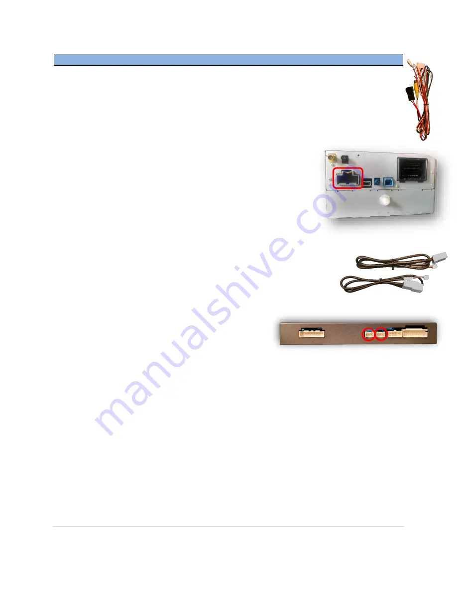
3.
From the back of the OEM radio, locate the 20-pin gray plug
and connect the provided
CAN T-Harness
between the OEM
plug and the radio.
a.
The other end of this cable connects to the interface at
the plug labeled
‘CAN1’.
b.
The Yellow RCA on this harness only gets used if the
vehicle already has an OEM reverse camera and you’re
adding an AUX video source or HDMI, etc. (see diagram, page 4)
4.
Connect the provided male
GVIF-OUT
cable directly to the radio unit.
5.
Connect the provided female
GVIF-IN
cable to the cable previously
removed from the radio unit (heads up to OEM screen).
6.
Connect the other ends of the provided GVIF video cables back to the
GM-GVIF interface a their appropriate connectors (these are labeled)
7.
Connect the provided
Power/CAN Harness
to the main power plug on the GM-GVIF
interface.
8.
Optional
: If adding a front camera or additional AUX video during this install, power it
with an ACC source and connect the video signal to the RCA among the provided
AV
Input Harness
labeled
‘AV
2
’ (yellow)
.
Note: Dip Switch 3 & 6 must be DOWN for proper
front camera setup. Also see OSD Menu settings, page 6.


